Research on Key Technologies of Underground Rescue Long-distance Video Transmission System
The key technical research of the long-distance rescue long-distance video transmission system involved in this article is the analysis, research and solution of the safety requirements of the underground rescue. By realizing 1500m of video transmission on inexpensive twisted pair cables, the image color and brightness are guaranteed , Contours, etc. are basically distortion-free, at the same time adapt to the consideration of waterproof, seismic, dust, high temperature, corrosive gases and other harsh underground environments, and meet the intrinsically safe explosion-proof design requirements, and finally commercialize it.
Related technical introduction
1 Twisted pair technology
Twisted-pair cable is a flexible communication cable that contains pairs of insulated copper wires. Because it has many advantages such as strong anti-interference ability, long transmission distance, easy wiring, and low price, it is cheap and therefore widely used. Due to the large attenuation of the signal of the twisted pair, the frequency of the signal cannot be too high when the transmission distance is long, and high-speed signals such as Ethernet can only be limited to 100m. For the video signal, the bandwidth reaches 6MHz, and if it is directly transmitted in the twisted pair, it will also be greatly attenuated. Therefore, to achieve long-distance transmission of the video signal on the twisted pair, it must be amplified and compensated. Twisted pair video transmission The device performs this function. With the addition of a pair of twisted pair video receiving and sending equipment, the image can be transmitted to 1 ~ 2km. Twisted pair and twisted pair video transmission equipment are very cheap, not only does not increase the cost of the system, but as the distance increases, its cost has dropped a lot compared to coaxial cable. Therefore, the use of twisted pair transmission in the monitoring system has obvious advantages.
Table 1 Main performance indexes of MAX435 and MAX436

2 Transconductance amplifier
The input signal of a transconductance amplifier (also called transconductance amplifier) ​​is a voltage quantity, and the output signal is a current quantity, and its gain is called transconductance Gm. The transconductance amplifier is a mixed voltage / current mode circuit. Because there are only voltages in it-current conversion stage and current transmission stage, but no voltage transmission stage, there is no large swing voltage signal and Miller multiplication effect, so it has It has the characteristics of high frequency bandwidth, high frequency performance and high signal conversion speed. The circuit structure of the transconductance amplifier is simple, and the power supply voltage and power consumption are reduced.
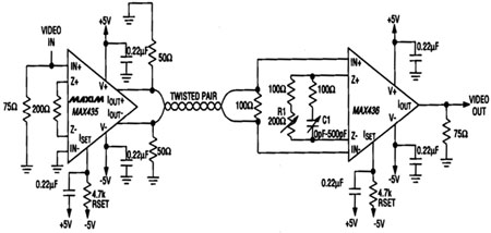
Figure 2 Video twisted pair drive / receive circuit
The drive circuit uses a transconductance amplifier to convert the single-ended voltage signal into a differential current signal, and transmits the video signal on the twisted pair through the current loop. The receiving end then restores the differential current signal to a single-ended voltage signal.
3 MAX435 and MAX436
Here, the transconductance amplifier uses MAXIM's MAX435 and MAX436 as the twisted pair video signal circuit driver. MAX435 and MAX436 are a new type of high-speed, wide-band transconductance amplifier, the pin arrangement is shown in Figure 1, Figure 2. They have the characteristics of ideal differential, high impedance input and current output. Due to these unique structures, the chip can provide accurate gain and eliminate closed-loop phase shift without negative feedback.
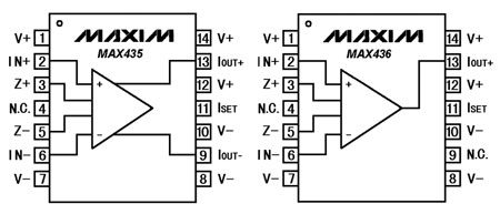
Figure 1 MAX435 and MAX436 pin arrangement diagram
Design and implementation methods
1 Circuit design
When the transmission distance is less than 1500m, the use of twisted pair to transmit the baseband video signal can also achieve good results. Compared with the use of traditional coaxial cables, pay attention to two points when using twisted pairs to transmit signals: balanced (differential) transmission to minimize common mode noise; proper termination to minimize reflection. Because the MAX435 and MAX436 can achieve a common-mode rejection ratio of 53dB at 10MHz. And the input and output impedances are very high, so it is especially suitable for such applications.
The actual circuit is shown in Figure 2. It can be seen from the figure that MAX435 and MAX436 form the driver / receiver of the twisted pair video transmission circuit. Only a differential output MAX435 can drive the balanced twisted pair (the input signal is based on ground), thereby eliminating the need for Balancing transformer or two single-ended output drivers. In order to achieve a balanced to single-ended line conversion, its receiver circuit uses a single-ended output MAX436. The 100Ω resistor from IN + to IN- makes the terminal connection of the line very reasonable. The transconductance network (from Z + to Z-) not only completes the gain adjustment (+ 6dB). And it also plays a role of line equalization, thereby improving the high-frequency gain of the receiver.
In the circuit in Figure 3, you can adjust R1 to increase the overall gain to compensate for ohmic losses to obtain the appropriate brightness, and adjust C1 (adding zero / pole pairs to expand the frequency band) to obtain the best color. Since the adjustment is made at the receiver, the user can adjust R1 and Cl while observing the screen at the receiver to obtain the best image.
2 Test results
Figure 3 (a) and Figure 3 (b) are the video pulse waveforms before and after adjustment seen from the monitor screen. The test results show that when this circuit uses a 165m long φ0.71mm anti-theft alarm to transmit NTSC baseband video signals with twisted pairs, the attenuation of the 3.58MHz burst signal is about 6dB. Although there is distortion, the monitor has automatic equalization compensation for signal attenuation (the attenuation compensation for color burst signals can reach 10dB), so the image quality is still very good, and there is no obvious phenomenon of color fading or horizontal resolution deterioration. However, if the attenuation is further increased, the chromaticity and horizontal resolution will deteriorate, making it difficult to see the displayed graphics.
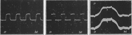
Figure 3 (a) Adjust the waveform before equalization (b) Adjust the waveform after equalization (c) Add 50Hz common mode noise voltage on the twisted pair
When this circuit uses a telephone twisted pair of 330m in length to transmit the NTSC video recorder video signal between the two buildings. The image quality is good. In addition, the 50Hz common mode noise voltage shown in Figure 3 (c) was added to each of the two balanced strands for testing.
This is because the MAX436 has a 60dB common-mode rejection ratio for 60Hz signals, so that this noise does not affect the image. If an unbalanced single-ended method is used to drive the cable, the difference in effect can be expected. Although the above experiment only used NTSC video signals, this circuit can still achieve a similar effect for PAL video signals with a carrier frequency of 4.43 MHz.
in conclusion
In many applications that do not require the cable to have a wide bandwidth, replacing expensive coaxial cables with twisted pairs not only reduces the cost of laying the line, but the differential interference currents induced by the two twisted pairs can cancel each other out. As long as the appropriate twisted wire is used, and the monitor at the receiving end performs impedance matching and automatic gain compensation (most TV monitors currently have this function), the distance to transmit the baseband (composite) video signal can be as long as 1500km, and the image The quality is not bad, and it can ensure that the image color, brightness, outline, etc. are basically distortion-free.
When the casing is processed in the later stage, due consideration should be given to the harsh underground environments such as waterproof, shockproof, dustproof, high temperature, and corrosive gas, and the intrinsically safe explosion-proof design requirements are met.
In summary, this technology meets the requirements of low cost, rapid laying, simple use, convenient maintenance and other requirements for underground rescue. And this technology can also be widely used in the single channel video signal transmission in the TV surveillance system in supermarkets, airports, schools and other units.
DIY Drone landing Gear, Carbon Fiber Landing Gear For Drone, Multi Rotor Landing Gear,Electric Retractable Landing Gear
DIY Drone landing Gear, Carbon Fiber Landing Gear For Drone, Multi Rotor Landing Gear
shenzhen GC Electronics Co.,Ltd. , https://www.jmrdrone.com