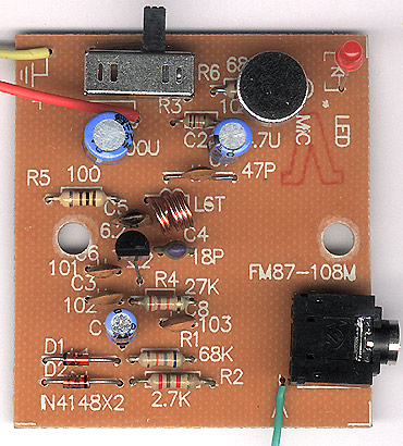
Circuit diagram of self-made simple wireless FM microphone
The following is the circuit diagram of the FM wireless microphone. The circuit is very simple and there are no extra components. The high-frequency transistor V1 and the capacitors C3, C5, and C6 form a capacitive three-point oscillator. For beginners, we don't want to think about the specific working principle of the capacitor three-point type for now. We only need to know that this circuit structure is a high-frequency oscillator. The load C4 and L of the triode collector constitute a resonator. The resonance frequency is the transmission frequency of the FM microphone. According to the parameters of the components in the figure, the transmission frequency can be between 88 and 108MHZ, which just covers the receiving frequency of the FM radio. By adjusting the L The value (stretching or compressing coil L) can easily change the transmission frequency, avoiding FM radio. The transmitted signal is coupled to the antenna through C7 and then transmitted. 
JIANGYANG Special Cables are shipboard wire, diesel engine dedicated cable, sensor dedicated cable, profibus cable, solid PE insulated radio frequency cable with solid PE dielectric, coaxial cable with physical-foamed polyethylene insulation used in CATV systems, RG Serials polyethylene insulation coaxial cable, muticore and symmetrical pair/quad cable for digital communications horizontal floor wiring-solid polyethylene insulate.
Wire Cable,Special Cable,Tinned Copper Wire,Flame Retardant Shipboard Flexible Wire
Jiangsu Jiangyang Special Cable Co,.Ltd. , https://www.jymarinecable.com