With the successful use of aircraft flight data recorders in air transportation management, vehicle driving status recorders have been used in large numbers in many countries and regions. As early as 1990, the European Community passed legislation to install a driving recorder on vehicles, and specified that commercial vehicles must install a driving recorder. This legislation requires its 15 member states in Europe to install the device for 9 million commercial vehicles in use within ten years. The United States, Japan, Malaysia and Hong Kong and other countries and regions have also widely used car driving state recorders. Statistics show that the use of automobile driving state recorders has reduced the traffic accident rate by 37% to 52%, greatly reduced the casualties and property losses, and produced significant social and economic benefits. It can be seen that accurately recording the operation process is extremely important to prevent accidents before they happen.
The vehicle driving state recorder can objectively and comprehensively record the various states of the vehicle driving and the driver's operating behavior at the time of the traffic accident, and provide a true, effective, and scientific vehicle driving originality for the traffic accident analysis Data, and can provide accident analysis functions to help relevant departments quickly determine the cause of the accident to protect the legitimate rights and interests of both parties (or parties); in normal operation, it is also a powerful tool for the management department to strengthen supervision and management to help management The personnel have a comprehensive understanding of the operation of the car; when the vehicle fails, it can also provide a fault diagnosis function to provide a reliable and accurate scientific basis for the maintenance personnel to judge the fault. The promotion of vehicle driving status recorders will play an important role in preventing serious traffic violations such as fatigue driving and vehicle speeding, restricting driving behavior of drivers, preventing road traffic accidents, ensuring vehicle driving safety, and improving operational management.
1 System composition and main functions
The vehicle driving status recording system is mainly composed of a vehicle driving status recorder, a handheld code reader and a management computer. The recorder is installed on the car to monitor and record the driving data of the vehicle in real time; the handheld code reader is composed of a handheld computer and application software, which is used to control and operate the operation of the recorder and read data from the recorder through the RS232 serial port ; The management computer is used for statistics, reports, storage and query of the original recorded data.
The recorder is the core of the entire system, and its main functions are as follows:
(1) Real-time monitoring and recording of various status information of the car driving such as time, speed, idle speed, overspeed, mileage, door switch, brake status, direction light status, near and high beam light, engine speed, engine abnormality, engine oil pressure, Temperature etc.
(2) The operation data is stored in the large-capacity serial flash memory, even if the power is turned off, the data will not be lost.
(3) Overtime (fatigue) alarm and record function, so as to effectively restrain the driver from driving fatigue and ensure the safety of long-distance transportation.
(4) Graded overspeed alarm function. Users can set three-level speed limit according to their needs. When the vehicle is overspeeding, it will receive different speed limit classification sound and light alarms, so as to effectively curb speeding and ensure driving safety.
(5) License plate number, car model, speed limit value and other data can be conveniently written or modified online through the handheld code reader.
(6) Equipped with GPS interface, which can easily expand GPS time, communication, positioning, information service and other functions.
(7) It has a standard RS232 interface for communication with handheld code readers and management computers.
(8) The management software can statistically analyze the driving speed, mileage, parking times, parking time, overspeed times, overspeed time, and the time of receipt and departure at any time, and provide various data that the management cares about.
2 Recorder hardware design
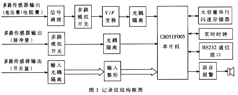
According to the functional requirements and working characteristics of the recorder. The design is mainly considered from the aspects of operational reliability, accuracy of recorded data and data storage capacity. The structural block diagram of the recorder is shown in Figure 1. It mainly includes single-chip microcomputer and its peripheral circuits, voltage, resistance, pulse and switch sampling circuits, real-time clock circuit, data storage circuit, sound and light alarm circuit, RS232 communication interface circuit Various car sensors, etc.
2. One-chip computer
Adopt C8051F005 one-chip computer that Cygnal Company produces as the control core. In this recorder, the PCA timer array completes the V / F conversion pulse counting; 2 voltage comparators realize battery overvoltage and undervoltage detection; use on-chip temperature sensor to achieve temperature detection; I / 0 port realizes switch detection; SPI interface controls ISD4004-16 chip to complete voice alarm, read and write of real-time clock chip MAX6902 clock and read and write of data storage chip AT45DB081B; on-chip RS232 port uploads the recorded data to the host computer. It can be seen that using a single chip of C8051F005 single chip can complete the control and detection of the system, which greatly simplifies the system hardware design and significantly reduces the system cost. 2.2 Sensor selection
The working environment of the sensor in the car is very harsh, so the requirements for the sensor are also very strict. These sensors must withstand temperature changes from a temperature of 40 ° C to + 150 ° C, and require high accuracy, good reliability, fast response, strong anti-interference and anti-vibration capabilities in order to accurately detect the relevant status of vehicle operation in real time and These states are converted into electrical signals for single-chip processing.
2.3 Signal detection
The output signals of automotive sensors are generally voltage, resistance, pulse signal, and switching value. The detection methods of these signals are introduced below.
2.3.1 Voltage signal
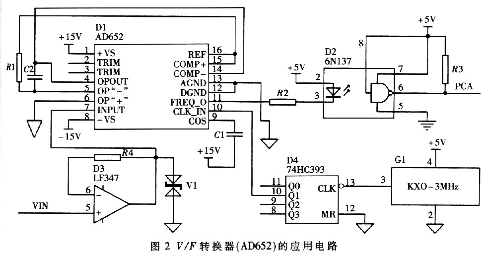
In order to improve the anti-interference ability and detection accuracy, the voltage signal is first converted into a standard signal of 0 to 5V by a signal conditioning circuit, and then converted to a pulse amount by V / F conversion, and then processed by the PCA array of the C8051F005 single-chip microcomputer after being isolated by the optocoupler . The application circuit of the V / F converter is shown in FIG. 2, in which the 3MHz pulse signal output by the active clock oscillator is divided by 74HC393 to be the external clock source of AD652.
2. 3 2 Resistance signal
The resistance signal is first converted into a standard signal of 0 ~ 5V by a Wheatstone bridge, and then converted to a pulse amount by V / F conversion, isolated by an optocoupler, and finally counted by the PCA array of the C8051F005 microcontroller.
2.3.3 Pulse signal
The pulse signal isolated by the optocoupler is directly counted and processed by the PCA array of the C8051F005 microcontroller.
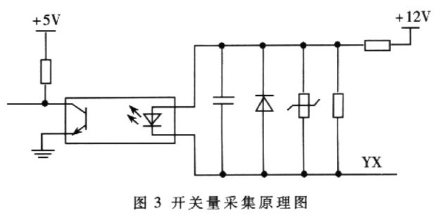
2.3.4 Switch signal
The schematic diagram of the switch acquisition is shown in Figure 3. When the working status of the brake and turn signal changes, its auxiliary contact will be connected to the + 12V Power Supply of the YX circuit. At this time, the optocoupler is turned on, and its output state changes. It is read through the I / O port in the single-chip interrupt service program Just take this state, its motion resolution can reach lms.
2.4 Voice alarm
When the system has a speeding alarm, the high-brightness red LED luminous tube flashes, and the voice alarm function is activated at the same time, and a warning voice of "speeding, please note" is issued.
The recorder uses a single-chip voice recording and playback circuit ISD4004-16 as the playback chip. The ISD4004-16 chip has a working voltage of 3.3V, a single-chip recording and playback time of 16 minutes, up to 2400 segments, and good sound quality. It is suitable for mobile phones and other portable electronic products. The chip uses CMOS technology, including an oscillator, anti-aliasing filter, smoothing filter, audio amplifier, automatic squelch and high-density multi-level flashing memory array. The chip design is based on that all operations must be controlled by the single chip microcomputer, and the operation commands can be sent through the serial communication interface SPI; while using multi-level direct analog storage technology, each sample value is directly stored in the on-chip flash memory, so it can Very real and natural reproduction of speech, music, tones and effects sound, avoiding the quantization noise and "metallic sound" caused by quantization and compression in general solid-state recording circuits; the sampling frequency is 4.0kHz, and the on-chip information is stored in the flash memory, It can be stored for 100 years (typical value) in case of power failure, and recorded 100,000 times repeatedly. In this recorder, the content of voice alarm is divided into 64 segments, which can be freely combined during playback.
2.5 Real-time clock
In order to accurately record the sampling time of the data, the recorder uses a serial clock chip MAX6902 with an SPI interface. The MAX6902 can work in a wide Power Supply range of + 2V ~ + 5.5V. The package is SOT23-8. The chip has 31B SRAM. It has the advantages of small size, simple peripheral circuit, good running stability, high accuracy, low power consumption, etc. It can meet the time requirements of the recorder.
2.6 Data storage
Because the amount of data to be recorded is relatively large, the recorder requires a large-capacity memory with a power-down memory. By comparison, the flash memory AT45DB081B produced by ATMEL is used. AT5DB081B is a serial interface; adopts 0 ~ 3 method of SPI interface to communicate with C8051F005 single-chip microcomputer, almost no external components are required, high integration, large data storage, data power-down preservation; working voltage is 3.3V, working current is 4mA (Only 2μA in the standby state); its main memory has 4096 pages, 264B per page, and the total capacity is 1056KB (about 8Mb), and the data stored in the main memory is not lost after power-off. In addition to the main memory, the AT45DB081B also has two data caches with a capacity of 264B. The cache can be used as a buffer area for data exchange between the main memory and the outside. It can also temporarily store some temporary data. The cache is easy to read and write, but it is powered off Data will be lost. AT45DB081B uses serial method to read and write data, with fast read and write speed, the transmission time from page to cache is about 80μs, and is compatible with CMOS and TTL level input and output.
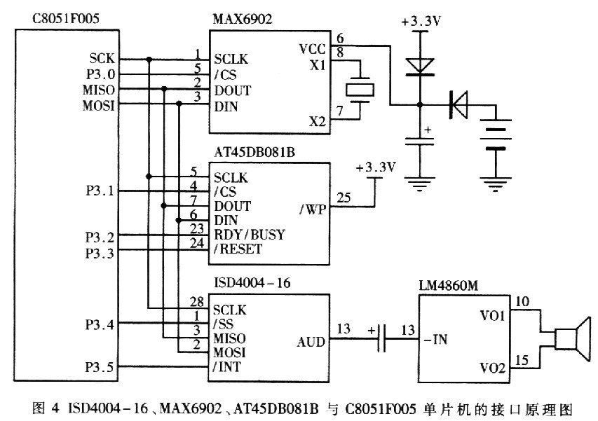
The interface schematic diagram of ISD4004-16, MAX6902, AT45DB081B and C8051F005 microcontroller is shown in Figure 4.
2.7 Anti-disassembly design
In order to prevent the recorder from being disassembled illegally, the system adopts an anti-disassembly design. In a normal state, the spring presses a key switch and the switch closes; when the recorder housing is disassembled, the spring pops up and the key switch is opened. Through the I / O port of the single-chip microcomputer, the state of the switch is periodically read and the change of the switch state is recorded and an alarm is reported.
3 Software design
The system software mainly completes two functions: (1) Real-time detection and recording of the driving status of the car, and sound and light alarm when a fault is detected. (2) Upload the recorded data to the host computer through the RS232 port for daily management and accident diagnosis.
The design of the software is completely in accordance with the structured program design plan, and the entire program is divided into several program modules according to the functions, so as to facilitate debugging and inspection. Using Keil C51 language programming. After the software in this design is edited, compiled, connected, and debugged in the integrated environment of KeilμVision2 V2.05, the program is directly downloaded to the C8051F005 microcontroller (ISP) through the JTAG interface. The program mainly includes: main program, analog quantity acquisition program, switch quantity acquisition program, pulse quantity acquisition program, data storage program, clock processing program, fault processing program, voice alarm program and serial communication program, etc.
4 System reliability design
As a driving condition recorder of a car, the working environment in the car is very bad. Therefore, how to ensure the stability and reliability of the system is very important.
Although the system hardware has been carefully designed, such as multilayer printed boards, reliable component selection, optocoupler isolation of input and output, the use of power input and output filters, hardware watchdog, etc., it has a strong anti-interference Function; but because the working environment of the recorder is more complicated. To ensure the absolute reliable operation of the system, the above measures are not enough, but also need to be considered from the software design to enhance the system's comprehensive anti-interference ability.
The direct result of the system encountering interference is that the program runs away. In software design. Mainly considered from the aspects of software modular design and event-driven approach, instruction redundancy and software traps, multiple copies of important software variables, software reentrant design and digital filtering, in order to enhance the system's comprehensive anti-jamming capability. Practice has proved that these measures have achieved good results.
The recorder strictly follows the requirements of automotive electronic products, fully considers the interior environment of the vehicle (such as electromagnetic interference, vibration, temperature, humidity, etc.), in the various steps of circuit design, electronic components selection, structural design, connector selection, etc. They are strictly in accordance with the corresponding electronic equipment standards and have passed various environmental tests. Since it was put into operation, it has achieved good results and can fully meet the needs of real-time recording of vehicle driving data.
ZhenHuan's junction box led drivers is the most compact metal case LED driver on the market with UL/CUL 8750 listed. The series led driver is class 2 rated and designed to provide Aluminum material housing and Iron material Housing for outdoor and indoor use. Encased in a low profile coated metal case with junction box, to enable easy installation that complies with electrical code requirements.
China 12v Led Transformer,Dimmer Driver,Led Strip Enclosures Drivers,Ac Led Transformers,Low Voltage Transformer Outdoor,Led Driver Junction Box
Shenzhenshi Zhenhuan Electronic Co Ltd , https://www.szzhpower.com