A telephone voice query and control system is introduced, the hardware and software of the telephone voice card are described, and the method of designing the system using VC ++ 6.0 multithreading technology and ADO parameterized query technology is given. 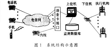


Keywords: telephone, voice, control, multithreading, ADO
1 Introduction
The monitoring and control system with PC has been widely used in many fields. Because we can only query and control the monitoring situation of the entire system in the monitoring center, so in work, especially when repairing the controlled equipment, often need a few people in the remote monitoring center and the controlled equipment. Busy from time to time, when problems are found, effective measures cannot be taken as soon as possible to solve them, resulting in unnecessary economic losses. At the request of a certain unit, this article designs an interactive telephone voice query and control system. It can not only query all accessible data of the unit, but also carry out key temperature monitoring and remote control of several large motors, so as to optimize management and improve work efficiency. It can also expand some personalized functions according to user needs, and is a new type of system with market prospects.
2 System hardware design
2.1 The working principle of the system
The hardware part of the telephone voice query and control system is mainly composed of the upper computer (PC), the lower computer, the executive agency, the telephone voice card, the external line (ordinary local telephone line) and the internal line. The system structure is shown in Figure 1. Users can use dual-tone telephones or mobile phones and other communication tools to call the system phone of the monitoring center from anywhere. The ringing signal passes through the telephone network to the upper computer through the voice card interface. After the system detects the ringing, it connects the phone and plays the prompt tone. When the user presses the telephone keypad, the upper computer analyzes the transmitted dual-tone multi-frequency code DTMF and converts it into a computer command. If the query command is received, the corresponding measurement and control database is queried, the host computer converts the query result into voice information, and then broadcasts it to the user through the voice card interface and the telecommunications network; if the control command is received , The control amount is calculated by the control algorithm, the host computer transmits the information to the lower computer through communication, drives the corresponding execution mechanism, and then uploads the execution status of the control command, the host computer converts it into voice information and plays it to the user , And display status information parameters, record the control log in the database for future statistics and analysis. If the system detects an on-hook signal or waits too long for dual-tone messages, the system will hang up the phone.
Under the non-control state of the upper computer, the lower computer continuously uploads the monitoring data to the upper computer, and records the valid data in the database. When the monitored data exceeds the predetermined value, it generates warning information.
2.2 Introduction to Phone Voice Card
Telephone voice card, namely "computer and telephone voice processing card", is a product of CTI (Computer TelecommunicaTIon IntegraTIon) technology. It contains analog telephone voice processing card and digital trunk interface voice processing card. This system uses an analog voice card. As a key interface device between the public telephone network and the computer, it is responsible for detecting and executing various telephone information. The development of domestic telephone voice card technology (except PC interface technology) mainly uses time division switching technology, which is evolved from the idea of ​​program-controlled switches. At present, technologies such as time division switching, voice compression, dedicated or general-purpose DSP (Digital Signal Processing) technology and PC interface are very mature. Each card has multiple channels independent of each other. According to the different needs of each channel, different functional modules can be selected. The voice card generally has the following main modules: interface, playback, recording, wire, fax, voice control recording, etc. Interface modules are divided into user modules (internal module) and relay modules (external module). The user module can directly drive the phone, connect the phone to this module, and go off-hook to work. The trunk module connects the telephone trunk line of the telecommunication network or the subscriber line of the small program-controlled switchboard, which is equivalent to a telephone.
The voice card supports two kinds of buses, namely ISA (Industry Standard Architecture) with I / O and IRQ set up during installation and PCI (Peripheral Component Interconnect) that can be plugged and used.
The software provided by the telephone voice card manufacturer with the card includes the underlying driver (dynamic link library DLL) and the secondary development interface program. Each channel can be programmed by software (such as VC ++, VB, Delphi, C / C ++, VFp, etc.) to complete the following basic functions:
· Automatically detect the ringing signal of the outside line and the off-hook action of the inside line;
· Control the picking up and hanging of the outside line, the feed or ring current of the inside line;
· Play digital computer voice files to the telephone line;
· Record telephone voice into digital computer voice file;
· Receive the user's telephone key code, that is, dual tone multi-frequency code;
· Detect the status of various signal tones returned by the telephone line, such as dial tone, busy tone, ring back tone, etc .;
· Any two channels on the calling card can be connected to talk to each other. When the card is equipped with both internal and external lines, the internal and external lines can also be connected to talk;
· Software adjustable voice compression ratio.
2.3 Design of lower computer
Through comparison, this article selects PIC16C57 microcontroller for design. It is an 8-bit machine with a reduced instruction set RISC and a fully static CMOS process; it is cost-effective and has a strong load capacity; it has 20 I / O ports, which can be used as monitoring ports and control ports respectively The maximum current drawn by the O port is 20mA, and the maximum sink current is 25mA, which can directly drive the LED. The temperature sensor adopts AD590, the temperature measurement range is -55 ℃ ~ 150 ℃, and its output current formula is
Iout = CT × (273.15 + t)
In the formula, CT = 1μA / K is the nominal temperature coefficient; t means Celsius. The current is amplified by the operational amplifier LM324 and output. The system adopts MAX232 circuit to serially communicate with the host computer through the RS232C interface. The drive circuit of the actuator is composed of devices such as MOC3081 and bidirectional thyristor. The input control current of the MOC3081 is 15mA, the zero-crossing detection voltage value is 20V, the output rated voltage is 600V, the maximum repeated surge current is 1A, and the output input isolation voltage is greater than 7500V. The trigger part of the drive circuit is shown in Figure 2.
2.4 Improvement of telephone communication lines
The quality of the telephone communication line is one of the important guarantees for the reliable operation of the system. The transmission frequency band of the telephone is 300 Hz to 3400 Hz. If there is interference noise in the phone, first check whether the phone line is far from the interference source. If the telephone line is too old, there is corrosion in the line, poor insulation of the telephone line or contact of the telephone line core with other conductors (such as aluminum alloy doors and windows) will cause its electrical performance to decline, transmission error rate rise and serious Noise such as communication or broadcasting. It should be replaced with a new wire, and the connection point should be connected. If there is still interference noise in the phone after that, you can connect a simple anti-interference filter circuit before the phone line is connected to the phone and the system (as shown in Figure 3). The component parameters can be calculated by the formula
Obtained, and finally determined by experiment. Where f is the interference frequency that needs to be filtered, XC is the capacitive reactance, and XL is the inductive reactance; the ground wire in the circuit must be reliable, otherwise the circuit may be invalid, or even the opposite.
3 System software design
3.1 The composition of the software
The lower computer program of this system mainly includes starting self-test module, AD conversion, data processing module, communication module, input and output module and so on. In order to solve the problem of jumping after the program is disturbed, put a SLEEP instruction at the end of each memory page. The watchdog instruction is not used in the delay waiting program of less than 18ms, and must be used in the delay waiting program of more than 18ms. CLRWDT instruction. When the system is running, due to the characteristics of components such as resistance, capacitance, amplifier, etc., the error of the parameters will directly affect the performance of the entire system. Therefore, there must be an error correction algorithm in the data processing module.
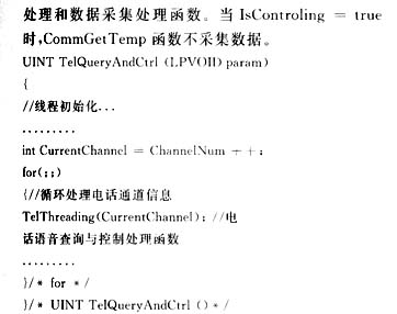
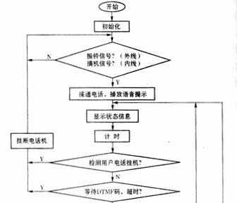
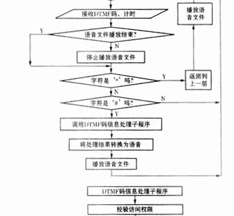
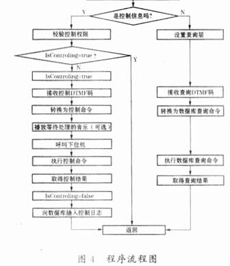
The upper computer software is mainly composed of program modules such as telephone voice processing, database processing, communication processing and system maintenance. The telephone voice processing program is to call off-hook and on-hook control, record and play voice control, receive and send DTMF codes, detect various signal tones, detect the busy / idle state of the telephone channel and calculate the control amount for each telephone channel by calling the underlying driver software. When playing multiple digits (such as 123, 2002), the pre-recorded voice file corresponding to each digit can be played continuously in sequence using combined playback. The voice processing module must have timeout control to wait for user information commands to avoid never hanging up. The program flow is shown in Figure 4. The database processing module is mainly for data management such as querying the database, recording control logs, and generating analysis reports. The communication processing module uses the MSComm object to call the lower computer in the format of 9600, N, 8, 1 and send and receive information to the lower computer.
3.2 Software design ideas
The telephone voice query and control system is based on operating systems such as Windows98 or WindowsNT. We can choose the clock interrupt polling method or the multi-thread (MulTIthread) method to design. In order to make the system have strong parallelism and high program efficiency, this system uses multi-line programming. In order to ensure the safety and effectiveness of data and control, the system uses a multi-thread design. In order to guarantee the safety and effectiveness of data and control, the access and setting of shared variables in software design should take synchronization, mutual exclusion and critical area operations.
This article uses the multithreading support provided by the MFC class library in Visual C ++ 6.0 for design. MFC distinguishes between two types of threads: Worker Thread and User Interface Thread. The main execution thread of the application is a user interface thread. We can write system initialization code in this thread and call the AfxBeginThread function to start the worker thread.
The worker thread is a function in the program that completes the parallel work of the thread. Telephone voice query can be written in the worker thread
3.3 System software access database
This system uses ADO (ActiveX Data Object) technology to operate the Oracle database in a shared manner. In order to improve the query speed of the system, indexes should be added to the tables in the database. If the system only performs query operations, you can specify to connect to the database in read-only mode and forward-only mode. Because the query statement is executed multiple times with different query conditions, the most effective method is to use the ADO Command object to parameterize the query (of course, the stored procedure is also a method). To this end, the following steps are required when writing a program:
(1) Create a SQL SELECT statement, using question marks to represent parameter placeholders (such as Where AdmID =?);
(2) Create an instance of the ADO Command object;
(3) Create an ADO Parameter object for the first parameter by calling the CreateParameter method of the Command object (such as Adm Cmd-> CreateParameter (L "AdmID", adBSTR, adParamInput, 0));
(4) Use the Append method of the Command object to add the Parameter object created in the previous step to the Parameters collection of the Command object;
(5) Repeat steps (3) and (4) to create other parameters for the query statement;
(6) Call the GetParameter method of the Command object to access the Parameters collection;
(7) Use the GetItem method of the Parameters collection to retrieve the first ADO Parameter object it contains;
(8) Assign value to the Value property of the Parameter object (such as GetItem ("AdmID")-> = _bstr_t (Channels [Chn]. AdmII));
(9) Repeat steps (6) ~ (8) to assign values ​​to other parameters;
(10) Call the Execute method of the Command object to execute the query, and return an open Recordset object;
(11) Convert the Field value of the Recordset object into a voice file for playback.
In addition, in order to more effectively improve the efficiency of retrieving multiple rows of records, you can use the GetRows method of the Recordset object to copy the records to a heterogeneous two-dimensional safe array for operation.
4 System scalability
According to the characteristics of this system, we can further expand some functions: add a lower computer with DTMF code for monitoring, use DTMF code to connect and pass information into the system, so that it can have a small The ability of the device with data volume to perform remote monitoring; when the host computer processes the parameters that deviate from the requirements, the system administrator's phone or mobile phone number is dialed to the telecommunications network through the voice card, thereby forming an automatic remote alarm function; the system can periodically remind What kind of work should the duty staff do at this time (such as night inspection), therefore, it can effectively manage the progress of some work of the monitoring center.
The system not only saves hardware cost, is flexible and widely used, but also has a short development cycle and high reliability, which has been well received by users.
references
1 Wang Youxu, Xu Jie, Li Lacheng. PIC series microcontroller interface technology and application system design. Beijing: Beijing University of Aeronautics and Astronautics Press, 2001
2 [US] Jim Maloney, Tian Yu, Liu Yun, Zheng Yifeng. Visual C ++ 6.0 DCOM Development Guide. Beijing: Tsinghua University Press, 2000
Electric Infrared Ceramic Cooker
Electric Infrared Ceramic Cook,Ceramic Cookware,Electric Ceramic Cooker,Kitchen Ceramic Electric Infrared Cooker
Shaoxing Haoda Electrical Appliance Co.,Ltd , https://www.hotplates.nl