Design and Analysis of TPMS System Based on MPXY8020 Sensor
With the rise of the global automotive electronics industry and people's continuous pursuit of informationization and intelligence of automobile safety, automobile tire pressure monitoring system (TPMS) has become another emerging automobile safety industry after airbags and ABS.
The TPMS currently appearing is mainly divided into indirect and direct. Indirect TPMS uses the ABS tire speed sensor to measure the rotation speed of each tire to determine the tire pressure. Although the system has the advantages of no battery and strong durability, the accuracy and reliability are poor. The direct TPMS system is mainly used to monitor the tire pressure automatically when the car is running. It can provide early warning of tire blowout caused by tire leakage and low tire pressure and high temperature and high tire pressure to ensure driving safety, so it has gradually become the mainstream of the market. This article mainly introduces the design of direct TPMS system based on MPXY8020 sensor, and analyzes the design difficulties of direct TPMS.
TPMS system block diagram and system working principle
The TPMS system consists of several transmitting modules and one receiving module. Figure 1 is a block diagram of the transmitter module.The transmitter module is installed in the tire.The pressure and temperature of the gas in the tire can be measured by the pressure and temperature sensor.The central processor at the transmitter is responsible for data processing, and the transmitter ID number, pressure, temperature, etc. After framing, the information is sent to the RF transmitting circuit through Manchester encoding, and finally the RF circuit modulates the data FSK / ASK and transmits it through the transmitting antenna. The entire transmitter module is powered by a battery.
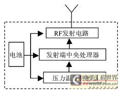
Figure 1 launch module
Figure 2 is a block diagram of the receiving module. The receiving module is installed at the front of the cab where it can be easily seen by the driver. The RF receiving circuit receives the wireless signal of the transmitting module through the receiving antenna, and demodulates and decodes the received signal to the receiving central processor. After processing the data, the central processor displays the pressure / temperature value of each tire according to the ID number. In the corresponding position of the display, the driver can always know the pressure and temperature information of each tire to ensure driving safety. If the tire is abnormal, the receiving module will automatically alert the driver in time. The receiving module can use car power | voltage regulator or battery.
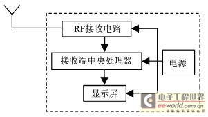
Figure 2 receiving module
Transmitter module design based on MPXY8020 sensor
The design of the transmitter module in the TPMS system uses Motorola's MPXY8020 and 68HC908RF2. The former is a capacitive pressure and temperature sensor chip, and the latter is an MCU and RF transmitter circuit integrated chip.
Transmitter hardware circuit design
MPXY8020 is a multi-functional, low-power sensor chip dedicated to TPMS system. In addition to the pressure and temperature sensor circuits, it also has a digital interface circuit with internal wake-up function, as shown in Figure 3. The interface between the 8020 sensor and the MCU has 6 ports: S1 and S2 are the 8020 working mode control ports. According to the MCU's logic state control of these two ports, 8020 can work in low-power standby mode, pressure measurement mode, temperature measurement mode and measurement data Output mode; DATA and CLK are software-controlled serial interfaces for measurement data transmission; OUT port is a multiplexed port, 8020 in standby mode, it can wake up internally every 3s and wake up the MCU in an interrupt mode through the OUT port. When the 8020 is in the measurement data output mode, OUT is the logic state output of the internal comparator; RST has the function of resetting the MCU at 52min.
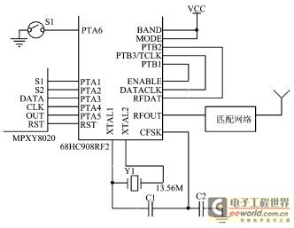
Figure 3 Transmitting circuit
It is worth noting that the A / D conversion of the 8020 sensor is a successive approximation feedback converter.The principle is that the 8020 has an 8-bit shift register.The MCU first inputs 10000000 binary data through the DATA and CLK ports of the 8020. The analog value of the D / A conversion of the bit register is compared with the actual measured value of pressure or temperature, and the state of the OUT port is judged. If the OUT port is low, it means that the approximation value is greater than the true value. At this time, the highest bit of the true value can be determined to be 0 ; If the OUT port is high, it means that the approximation value is less than the true value, and the highest bit of the true value can be determined to be 1. By analogy from high to low, the real measured values ​​can be approximated one by one, so that the MCU can determine the final pressure and temperature measurements.
68HC908RF2 internal high-performance 8-bit processor is mainly responsible for data transmission with the sensor, data analysis processing and data transmission and control with the RF transmission circuit. In the transmitter circuit in Figure 3, PTA1 and PTA2 are used as output ports to control the operating mode of 8020; PTA3 and PTA4 are used as outputs to shift the input measurement approximation value to 8020; PTA5 is the multiplexed end.When the MCU reads the measured value of the sensor, PTA5 Get the status of the comparator through OUT. When MCU is in power saving mode, PTA5 is used as the keyboard interrupt input port, and get 3s interrupt through OUT. In addition, S1 is a speed switch. When the car is running or stopped, the S1 switch can be turned on or closed, so that the MCU can effectively process the program according to the running state of the vehicle.
68HC908RF2 also integrates a multi-band FSK / OOK modulation circuit, its working mode is determined by the logic state of the digital control terminals (BAND and MODE). BAND selects the port for the working frequency band, sets BAND high, and selects crystal oscillator Y1 to be 13.56MHz. At this time, an RF signal with a carrier frequency of 434MHz is generated after 32 times the frequency. MODE is the FSK / OOK modulation mode selection port, set MODE high, the RF circuit works in FSK mode.
Although 68HC908RF2 integrates MCU and RF circuit in one, its interface circuit still needs external connection, as shown in Figure 3. PTB1 is used as the output control ENABLE of the RF circuit; PTB2 and PTB3 are connected to the RFDATA and DATACLK of the RF circuit as serial ports, and the pressure and temperature information after Manchester encoding is transmitted to the transmitting circuit in a binary data stream, transmitting The circuit then transmits in FSK mode. The FSK working principle is relatively simple. When the RFDATA input "1" or "0", it will cause the change of the output impedance of CFSK, thus switching the two load capacitors C1 and C2 of the crystal oscillator Y1, the change of the load capacitance makes the crystal oscillator There is a small shift in the resonance frequency, so that the FSK signal can be generated after frequency doubling.
Transmit module firmware programming
The firmware program of the transmitting module is relatively simple from a functional point of view, but considering the reliability and service life of the system, it places high requirements on the safety, economy and effectiveness of the program design. Especially relying on a 500mAh lithium battery TPMS transmitter to work for more than 8 years, in addition to excellent hardware design, the firmware program is particularly important to economically and effectively control the various circuits of the transmitter module.
Figure 4 is a simple program flow chart, considering the problem of power saving, the entire launch module is generally in power saving mode. When MPXY80203s interrupts and wakes up the MCU, the MCU immediately controls the 8020 to perform pressure and temperature detection and obtain pressure and temperature measurement values. The MCU then judges the measurement data to see if the tire pressure and temperature are in a normal state: if the tire pressure and temperature are normal, then judge the timing The time to send data, if the timing time is not reached, enter the power saving mode, the timing time, then framing, Manchester encoding, sending RF data, and finally enter the power saving mode. On the contrary, if the tire pressure or temperature is abnormal, it will directly enter the data sending procedure.
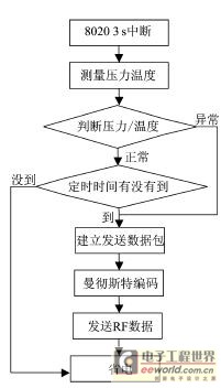
Figure 4 Launch flow chart
Receiver module design
The receiver of this system adopts Motorola's receiving chip MC33594 and central processor 68HC908GT16, and the display adopts liquid crystal display | display device.
Receiver module hardware circuit design
MC33594 is a high-sensitivity OOK / FSK demodulation chip with automatic gain control, which internally includes circuits such as mixing, intermediate frequency amplification, phase-locked loop, demodulation, data management, and SPI interface. The MCU can configure the internal registers of the MC33594 through the SPI interface to set the modulation type, data reception code rate, RF carrier frequency and other information of the receiving chip. Figure 5 is the TPMS receiving circuit.The MC33594 receives the RF signal transmitted by the transmitter through the receiving antenna, demodulates the RF signal and transmits it to the 68HC908GT16 (MCU) through the SPI interface in an interrupted manner.The MCU is responsible for processing data, displaying data, and when necessary. Start the alarm circuit.
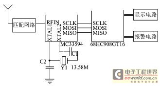
Figure 5 receiving circuit
Receiver firmware programming
The receiving procedure is similar to the transmitting procedure, although the function is simple, but from the perspective of reliability, especially when a receiver wants to receive data from 4 transmitters or more transmitters at the same time, the effectiveness and timeliness of the data received by the receiving program More important.
Figure 6 is a flow chart of the receiver program.Considering the validity of the received data, we design the SPI interrupt mode to receive the data.After receiving the data frame, the MCU parses out the ID number, pressure value, temperature value and other information of the transmitter, and then judges the transmission. Whether the ID of the device is the same as the ID stored in the receiver. If they are not the same, discard the set of data and enter the power saving state. If the IDs are consistent, the data is processed and the pressure and temperature data of the corresponding tires are displayed according to the IDs. When the pressure or temperature exceeds the normal range, the alarm can be promptly and accurately.
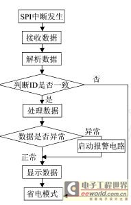
Figure 6 Receiving flowchart
Wireless communication and protocol
The design of TPMS system wireless communication is related to the reliability of data transmission of the entire system. The receiving chip MC33594 provides flexible software and hardware communication resources. Program the internal registers CR1, CR2, CR3 of MC33594 through software, set the carrier frequency of this TPMS system to 434MHz, and the wireless data transmission rate to 9600bps. The data transmission of the transmitting module and the receiving module adopts a fixed frame length, the format is: frame header (2 bytes) + transmitter ID (4 bytes) + pressure data (1 byte) + temperature data (1 byte) + status Information (1 byte) + check (1 byte) + end of frame (1 byte).
The frame header contains the synchronization header, preset ID information (for RF signal identification), header flag (binary Manchester encoding 0110), the synchronization header is used to wake up the internal circuit of the MC33594, and lock the RF carrier frequency through the PLL; preset The ID information is used to identify the matching of the system information; if the preset ID information matches, the data manager is started, and then it is judged whether the header arrives, and the data is officially received after the header is received.
Analysis of Difficulties in TPMS System Design
Signal reliability requirements
TPMS is a wireless transceiver system that measures tire pressure, temperature, etc., and involves safety information. Its signal reliability is always an issue to be considered in the design. The signal reliability includes two aspects: data reception rate and bit error rate. The data reception rate refers to whether the receiver can reliably receive each frame of data transmitted by the transmitter. It not only involves the sensitivity of the receiver and the transmission power of the transmitter, but also has an important influencing factor: when the transmitter is installed in the tire, it is received When the machine is put into the car, the car body itself is equivalent to a shielded box, and the attenuation of the signal is quite large. In addition, the data collision of multiple transmitters and the interference of the surrounding environment, etc., lead to a low data reception rate of the system. Bit error rate means that the signal transmitted by the transmitter causes the receiver to receive the wrong data information due to the interference of the external environment during the transmission, which reduces the reliability of the system.
In the TPMS design based on MPXY8020, we use a high-gain transmit antenna and matching circuit to make the transmit power meet the ideal design requirements, especially at the receiving end.In addition to the matching circuit design, on the one hand, according to the research and analysis of the radio transmission path on the car, A dual-antenna reception mode is used; on the other hand, according to the randomness and conflict of the multi-transmitter transmission signals, the data is transmitted by the time difference gap for transmission, and the reception mode of interrupting the reception loop processing is used in the design of the reception software. In this way, the TPMS signal reception rate can be as high as 98%. In addition, the software design uses a combination of multiple verification methods for the transmission data, which greatly reduces the bit error rate of the system.
Of course, frequent data transmission can increase the probability of the receiver receiving data, thereby improving system reliability, but this will greatly reduce the battery life.
Environmental requirements
As a product used in automobiles, TPMS has quite stringent environmental adaptation requirements, especially the transmitter, in addition to the wide temperature range, it also needs to meet many requirements such as waterproof, salt spray, vibration resistance, shock resistance, electromagnetic compatibility and so on. This puts high requirements on the raw materials, such as the working temperature of the battery must reach -40 ~ 125 ℃; the transmitter housing must use high strength, high toughness, high and low temperature resistant materials. The production process of TPMS transmitters is also very demanding, such as the use of sealing, grouting and other processes, as well as the design of many environmental tests in the production process.
The battery, one of the key components, uses TADIRAN's TLH2450 battery to meet the design requirements of temperature; combining the environmental requirements of the transmitter housing and based on the analysis of the characteristics of various plastic materials, the transmitter housing is designed using synthetic materials such as nylon and glass fiber It meets the design requirements of anti-vibration, anti-shock, high and low temperature resistance. In addition, the transmitter is sealed with glue, even if the transmitter is completely immersed in water, the data can be transmitted normally.
Volume and weight requirements
The TPMS launch module should be installed in the tire, so the volume cannot be too large, too large will cause great problems for the installation and disassembly of the tire; secondly, the launch module weight should be very light, otherwise it will affect the dynamic balance of the tire. Therefore, in the design of TPMS, the volume and weight of the transmitting module are strictly limited, which meets the design requirements of small size and light weight.
Service life requirements
The service life of TPMS generally needs to reach 8 to 10 years, which is indeed a difficult problem for the design of transmitters that rely on only a 500mAh battery (too large battery capacity will increase the size and weight of the transmission module). In addition to the extremely low power consumption of the hardware circuit design, the firmware design of the TPMS transmitter is very important. On the premise of ensuring the system reliability requirements, the transmitter's sensor measurement times and RF data transmission times must be strictly controlled. Therefore, designers often have to optimize the contradiction between system reliability and life requirements.
In the TPMS design based on the 8020 sensor, considering that the transmitter wakes up the MCU to operate in a 3s interrupt, its transmitter module is in the power-saving state most of the time, so the power consumption of the power-saving state is designed to reach below 0.6uA. Under the experiment of the battery's extreme life, based on the statistics of the number of transmitters, the life of the TPMS system is theoretically calculated to be more than 10 years.
Conclusion
Direct TPMS system faces many difficulties in product design. As an automotive safety product, more attention should be paid to its system failure analysis. With the continuous development of TPMS technology, the integration of new TPMS technology solutions is getting higher and higher, especially after integrating sensors, MCUs, and transmitting circuits into one, not only is the size and weight of the transmitting module smaller, its performance and functions Have been greatly improved, such as adding LF, LVD, acceleration testing and other functions, and even connecting the TPMS system to the vehicle electronic system through the CAN bus, so as to achieve information sharing.
Fast Recovery Diode (FRD) is a semiconductor diode with good switching characteristics and short reverse recovery time. It is mainly used in switching power supplies, PWM pulse width modulators, inverters and other electronic circuits as high-frequency rectifier diodes. Free-wheeling or damper diodes are used. The internal structure of the fast Recovery Diode is different from that of an ordinary PN junction diode. It belongs to a PIN junction diode, that is, a base region I is added between the P-type silicon material and the N-type silicon material to form a PIN silicon wafer. Since the base area is thin and the reverse recovery charge is small, the fast recovery diode has a short reverse recovery time, a low forward voltage drop, and a high reverse breakdown voltage (withstanding voltage).

Fast Recovery Stud Diode,Stud Type Fast Recovery Diode,Fast Recovery Diode,Stud Rectifier Power Diode
YANGZHOU POSITIONING TECH CO., LTD. , https://www.yzpst.com