**Introduction**
Ensuring data integrity during power outages is a critical concern for modern digital systems, particularly in industries such as telecommunications, automotive engineering, and industrial automation. Embedded systems often depend on uninterrupted power supplies, and data corruption can occur if operations involving hard drives or flash memory are interrupted. Automotive maintenance, diagnostics, and repair tasks heavily rely on storing operational states and tool locations, making it vital to preserve data even in the event of power disruptions.
Traditional backup power solutions have typically depended on high-voltage power supplies and large capacitors within boost-type power factor correction (PFC) circuits. These systems use a combination of high voltage outputs (350V to 400V) and large capacitors to provide enough energy to sustain critical loads during outages. However, many contemporary systems, such as modern vehicles, do not require AC/DC converters, and low-voltage power supplies are increasingly common. This shift has led to the need for alternative backup strategies.
All batteryless backup solutions hinge on the energy-storing capabilities of capacitors. The formula for calculating energy stored in a capacitor is:
\[ W = \frac{1}{2} C (V_{MAX}^2 - V_{MIN}^2) \]
Where \( C \) is the capacitance, \( V_{MAX} \) and \( V_{MIN} \) represent the maximum and minimum voltages, \( V_{OUT} \) and \( I_{OUT} \) denote the load voltage and current, and \( T_H \) is the hold time—the duration the output voltage remains regulated after the main power is interrupted.
**Three Simple Power Supply Retention Solutions**
Designers aiming to meet hold time requirements in low-voltage systems can increase capacitance (often through supercapacitors) or utilize a boost converter to generate higher voltages. While these solutions are straightforward with specialized ICs, they require additional components beyond standard DC/DC converters. This article explores two traditional approaches and introduces a more cost-effective option for shorter hold times that doesn’t necessitate extra controllers or capacitors.
**Supercapacitor-Based Power Retention Solution**
Consider a straightforward supercapacitor-based solution employing the LTC3110, a 2A bidirectional buck-boost DC/DC regulator and charger/balancer (detailed in [1]). The schematic of this solution is illustrated in Figure 1.
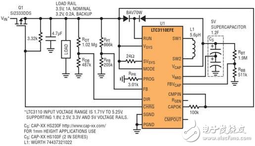
In Figure 1, the load and the LTC3110 converter are powered by the input voltage controlled via MOSFET Q1, which is typically active. When \( V_{IN} \) is present, the LTC3110 charges and balances the supercapacitor stack to ensure uniform voltage distribution between the two halves of the capacitor. When \( V_{IN} \) is interrupted, Q1 turns off, isolating the load from the primary power source and enabling the LTC3110 to discharge the stored energy into the load. Even as the supercapacitor voltage decreases from its full 5V to well below 3.3V, the LTC3110 sustains a stable 3.3V rail voltage. Resistors \( R_{DT}, R_{DB} \) control the flow of energy into or out of the storage capacitor, while \( R_{FT}, R_{FB} \) determine the load voltage, and \( R_{BT}, R_{BB} \) regulate the maximum voltage across the capacitor stack. This solution supports compact designs, reaching heights as low as 1mm, as seen in Figure 1.
**Boost Voltage Retention Solution**
Figure 2 demonstrates an alternative solution leveraging a less expensive (compared to supercapacitors) electrolytic or hybrid storage capacitor. This backup design centers around the LTC3643 (detailed in [2]).
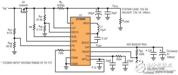
When the input voltage is present, the LTC3643 boosts it to a maximum of 40V. Upon a power interruption, it functions as a buck regulator, discharging the storage capacitor’s energy to the load while maintaining the pre-set voltage level. The resistor divider serves the same purpose as described earlier. To manage charging currents and prioritize load demands over capacitor charging, the LTC3110 employs resistor \( R_{PR} \), whereas the LTC3643 achieves this with a current sense resistor \( R_{S} \).
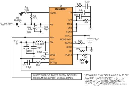
**A Cost-Effective Backup Solution with Minimal Components**
For projects requiring short hold times and budget constraints, the solution depicted in Figure 3 minimizes costs by sacrificing hold time. The LTC3649, usually functioning as a buck converter, switches to boost mode when the input voltage is lost. It discharges its internal output capacitor to maintain the critical load's programmed voltage.
**Conclusion**
This paper highlights DC/DC power supply retention systems spanning a broad input voltage range: 1.8V–5.5V (with LTC3110), 3V–17V (with LTC3643), and 3.1V–60V (with LTC3649). Each solution proves effective in automotive and industrial applications requiring data backup during power interruptions.
**References**
1. [LTC3110](http://LTC3110), LTC3110 Product Manual and Demo Circuit.
2. [LTC3643](http://LTC3643), LTC3643 Product Manual and Demo Circuit.
3. [LTC3649](http://LTC3649), LTC3649 Product Brochure and Demo Circuit.
Product features
High temperature resistant, glass fiber reinforced and flame retardant polyester is used as insulation material
Copper gold composite conductor with high conductivity is used, and the contact area of the conductor is plated with gold
It adopts shrapnel contact, which has the characteristics of integration, small volume, large current carrying capacity, soft plug-in, blind plug-in, self guidance and high dynamic contact reliability. This series of products can be interchanged with FCI's powerblade series and Tyco's multi-beam series
There are three sizes of center distance of power contact: 5.08mm, 6.35mm and 7.62mm
The length of power hole / signal pin can be selected in two sizes. The power rated current is 45A and the signal rated current is 2.5A
7.62MM Power+ Signal Power Connector
power connector is used in power module system. It can select the matching power + signal connector according to the need. The feature is that the number of power and signal contacts and the matching sequence can be selected arbitrarily while keeping the connector size and contact core number unchanged.
Plug (male) / socket (female) can be installed at 90 or 180 degrees. It supports mixed or independent combination of signal and power. The quantity range of power and signal is (2-16) pin and (12-128) pin respectively
Product features
High temperature resistant, glass fiber reinforced and flame retardant polyester is used as insulation material
Copper gold composite conductor with high conductivity is used, and the contact area of the conductor is plated with gold
It adopts shrapnel contact, which has the characteristics of integration, small volume, large current carrying capacity, soft plug-in, blind plug-in, self guidance and high dynamic contact reliability. This series of products can be interchanged with FCI's powerblade series and Tyco's multi-beam series
There are three sizes of center distance of power contact: 5.08mm, 6.35mm and 7.62mm
The length of power hole / signal pin can be selected in two sizes. The power rated current is 45A and the signal rated current is 2.5A
7.62MM Power+ Signal Power Connector
ShenZhen Antenk Electronics Co,Ltd , https://www.antenk.com