**Summary:** For fixed-frequency peak current mode PWM boost DC-DC converters, this paper proposes a design method for a current loop compensation circuit that is structurally simple and easy to integrate. The ramp generation circuit within the circuit converts the voltage on the on-chip oscillator’s charge-discharge capacitor into a current, producing a ramp current with stable characteristics and adjustable slope. The current sampling circuit employs SENSEFET technology combined with an optimized buffer, reducing losses while improving sampling accuracy. The entire circuit can be fabricated using a 0.6 µm 15V BCD process. Simulation results using Cadence Spectre indicate that the circuit effectively suppresses sub-harmonic oscillations, with a sampling accuracy of 77.9% and a compensation slope accuracy of 81.5%.
**Keywords:** Slope compensation; Current sampling; Current mode; V/I conversion
**Introduction:** Fixed-frequency peak current mode PWM (Pulse Width Modulation) DC-DC converters have gained popularity due to their advantages over traditional voltage-mode controls, including superior transient response, high output precision, and strong load capacity. As essential analog components, the slope compensation circuit and current sampling circuit form the foundation of current-mode PWM control and play a critical role in ensuring the stability of the current loop in such systems.
**1. Circuit Structure:** Figure 1 illustrates the block diagram of a typical peak current mode PWM Boost DC-DC control system. When the voltage feedback signal from the outer voltage loop is passed through the error amplifier and then to the PWM comparator, a triangular wave or trapezoidal sharp-angled composite wave, representing the peak value of the output inductor current, is generated. This signal is compared with the amplified voltage error signal (VE) to determine the PWM pulse turn-off threshold:
[3][4]
In addition to the technical details outlined above, the proposed circuit design also emphasizes the importance of minimizing energy losses while maintaining high performance standards. The use of advanced semiconductor processes like BCD allows for higher integration density and improved thermal management, making the circuit suitable for demanding industrial applications.
The next section will delve deeper into the specifics of the slope compensation circuit and its role in enhancing overall system stability. Furthermore, we will discuss how the V/I conversion technique improves the accuracy of current sampling, which is crucial for achieving optimal performance in power supply designs.
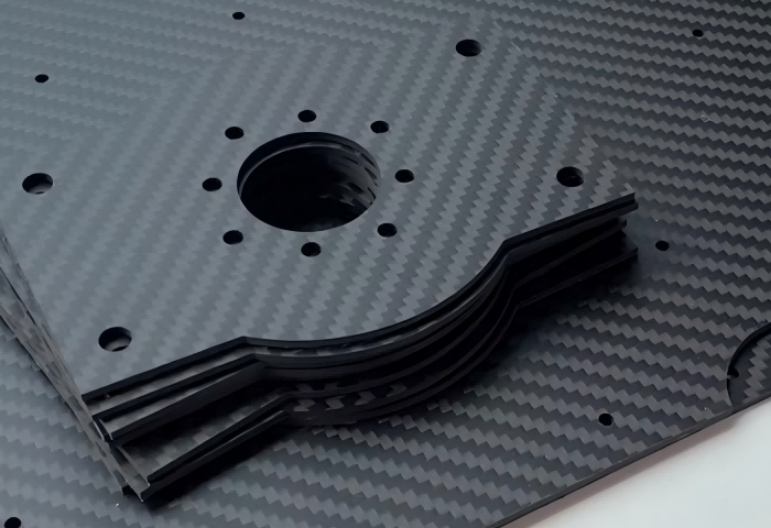
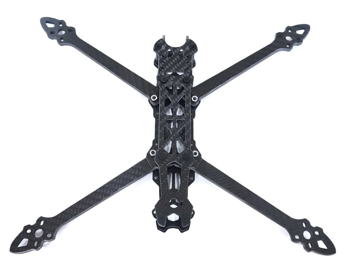
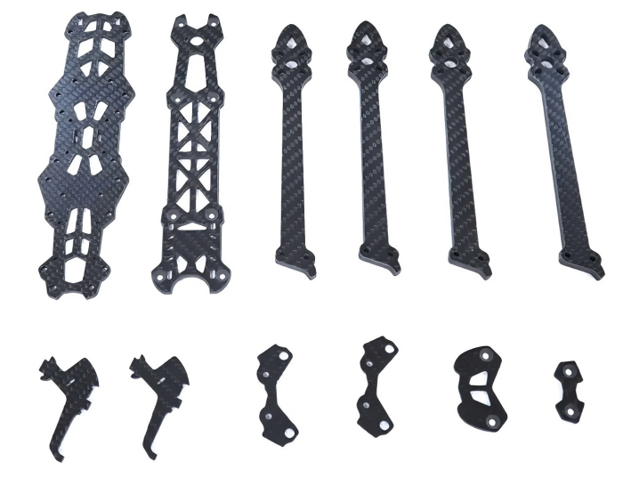
Mark4 V2 Mark4 7inch 295mm / 8inch 367mm / 9inch 387mm / 10inch 427mm 3K Full Carbon Fiber TrueX Frame for FPV Camera Kit Done:


Carbon Fiber FPV Drone Frame,FPV Drone TrueX Frame,Carbon Fiber FPV Frame
Jiangsu Yunbo Intelligent Technology Co., Ltd , https://www.fmodel-ai.com