Compared with thin film field effect transistor liquid crystal display (TFT-LCD), OLED has the advantages of fast response, full color, self-illumination, wide viewing angle, high contrast, low voltage, flexible display, etc., which can be better applied to mobile phones. MP3, small size dashboard, etc. OLED display has become a strong competitor of the next-generation flat panel display 15' with its excellent display performance. At present, there are many small and medium-sized OLEDs on the market, but the design of the driver interface circuit is very small. I intend to use STCllL60XE microcontroller as the microcontroller. The main controller of the OLED display module CMEL C0283QGLD-T. Try to achieve OLED full color still picture display in SPI mode.
CMEL C0283QGLD-T display module is 240xRGBx320 dot matrix 2.8 in full color OLED display module, integrated S6E63D6 driver "1, Figure 1 is the structural block diagram of S6E63D6. S6E63D6 is a special chip for OLED driver with controller, the largest It can support 240xRGBx320 dot matrix graphic display. The built-in capacity is 240x18x320 bit image memory (GRAM), and the image data can be written into GRAM to realize 65k, 260k color picture display. It has four programmable color display interface modes:
18-/16?/9/8-bit parallel interface mode, 18?/16/6-bit RGB interface mode, Serial Peripheral Interface (SPI) mode, and High Speed ​​Serial Interface (MDDI) mode. The S6E63D6 embeds a DC-to-DC voltage converter that provides the internal pixel drive voltage of the OLED module.
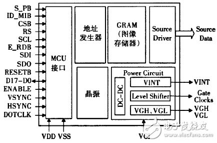
Figure l Block diagram of S6E63D6
Hardware circuit designTo achieve static picture display, image data needs to be pre-stored. The internal program space of the MCU is limited (60 k), which is not suitable for storing image data. The use of Flash memory as the image data storage area can effectively solve this problem. The MCU only needs to read the image data in the flash memory and then transfer it to the display module to realize the static picture display. System hardware block diagram shown in Figure 2, the whole system uses 5 V DC power supply, two power modules provide the voltage required for the entire control circuit and the voltage required for OLED display, microcontroller (MCU) module implementation with OLED module and flash memory The communication provides an online programming interface and a hardware reset interface for serial communication using the SPI protocol 18I.
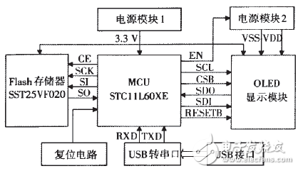
Figure 2 system hardware block diagram
Lithium Batteries 72V,Lithium Batteries 200A Rechargeable,Customized Rechargeable Lithium Battery,Lithium Ion Battery
Shaoxing Honyo International Trading Co., Ltd , https://www.honyopower.com