Many AC power systems that exceed a certain power level require power factor correction (PFC), which is a requirement of the power company or government. The PFC is located at the system input, behind the diode bridge rectifier, but before all input capacitors. The role of the PFC circuit is to ensure that the voltage and current at the input are in phase with each other. In other words, the PFC is the ratio of the average power to the apparent power delivered to the circuit load.
In addition to reducing apparent power, the PFC circuit helps to significantly reduce distortion on the input line. Without PFC, the THD (total harmonic distortion) generated by the load can adversely affect other circuits powered by the same grid. The PFC circuit optimizes the power factor while reducing THD. In many systems, the power factor is less important than the interference caused by high THD.
This article describes an easy way to design an extremely flexible and feature-rich PFC circuit using ADI's ADP1047 and ADP1048 digital PFC controllers with monitoring. Design work is done using an intuitive graphical user interface. The advantages of this approach are also discussed in conjunction with motor drive applications.
Different PFC circuits
PFC circuits typically use a step-up DC-DC converter topology and are located directly behind the AC rectifier bridge. This topology forces the input current to be in phase with the input voltage. As a result, the load appears to the AC power source to be a pure passive load resistor. For higher power levels, an interleaved topology can be used. The most common is the two-channel interleaving operation, which is no different than having the two boost converters be connected in parallel and sharing the load. In addition to PFC, a similar method is called "multiphase." The buck regulator uses the term "multiphase" for situations where current is distributed between different parallel buck circuits and the outputs are combined. In PFC, this feature does not use the term "phase" because it causes a lot of confusion. Multiphase is used for PFC circuits with more than one phase AC power input. Therefore, the term "interlace" is more commonly used when describing load power distribution among multiple parallel boost topologies.
In order to achieve very high power efficiency, it is also possible to use no bridge. In this case, the diode bridge rectifier can be omitted. In an interleaved operation with a diode bridge rectifier, the two channels alternate between each switching cycle. However, in a bridgeless topology, one channel switches during the positive half-wave period of the AC input voltage and the other channel switches during the negative half-wave period. Figure 1 shows the schematic of these three basic circuits. The simplest implementation is shown at the top, with the interlaced concept in the middle and the bridgeless configuration at the bottom. Of course, there are many other circuit solutions that are feasible. For example, for high power and high efficiency operation, interleaved operation can be combined with a bridgeless configuration. Obviously, this design requires many components and can become quite complicated. The ADP1047 is designed for single-channel PFC and the ADP1048 provides interleaved and bridgeless operation. To this end, it provides a current sharing function and two different PWM output signals.
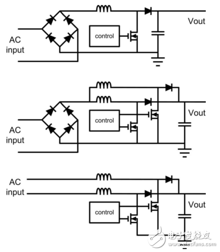
Figure 1. Different PFC circuits
Flexibility with digital PFC controllers
Most PFC converters are analog systems. However, with today's digital derivatives, such as Analog Devices' ADP1047 and ADP1048, designers have the flexibility to offer digital products. By replacing the hardware components with programmable digital filters, loop stability can be optimized for high speed operation, making the circuit stable enough. Although these devices use a current sharing mode control loop, there are actually multiple different loops that can be programmed independently. There are low and high line current filters, as well as fast voltage compensation filters.
The output voltage of the PFC can be set to vary depending on the load current. This can improve the power conversion efficiency of the entire system. In addition, the soft start feature can be adjusted very carefully.
Monitoring the voltage and current at the input of the system is very valuable
In addition to the digital control loop, the ADP1047 and ADP1048 provide precise voltage and current monitoring. They detect input and output voltages as well as input currents. The detected analog value is converted to a digital value by an analog to digital converter. The inductor current (equal to the input current) can be measured directly with the current sense resistor (highest accuracy) or indirectly with two current transformers and a power switch/boost diode in series. Regardless of the test method used, the test can be calibrated in the system to improve measurement accuracy. This calibration is usually done with the production test and the calibration values ​​are stored in the EEPROM of the ADP1047 and ADP1048. In addition to voltage and current, an external temperature sensor can be calibrated.
The measured voltage and current related information is used for operation, control and protection, but can also be provided to other circuits in the system for monitoring via PMBus. The input power of the PFC is of particular importance because it provides information about potential system failures. To help the system work safely and reliably, you can set different interrupts, such as flags. Voltage and current information as well as register settings can be accessed through the integrated PMBus interface.
Graphical user interface eliminates the need for programming skills
Experienced Power Supply design engineers are often not good at writing code, so the PFC solution takes the approach of reducing the digital aspects of the circuit to an easy-to-use graphical user interface (GUI). Figure 2 shows a screenshot of the software. All parameters that can be changed are graphically displayed on different settings and monitor screens. In this way, it is safer to evaluate and program the ADP1047 and ADP1048 because the internal state machine of these chips reduces the amount of room for the user to make mistakes compared to general microcontroller or digital signal processor programming.
An example of demonstrating GUI capabilities is to adjust the soft start feature. The activated input voltage threshold can be adjusted with a single mouse click. The inrush current time delay is then set. Surge control is used to pre-charge the output capacitor of the PFC circuit before the circuit is started. This is often done by relays or MOSFETs. The middle of the screenshot shown in Figure 2 shows how easy it is to adjust this surge timing. As shown at the bottom of Figure 2, the user can adjust the behavior of the soft start function itself. In this regard, the extra delay time before start-up and the rise time of the output voltage can be adjusted.
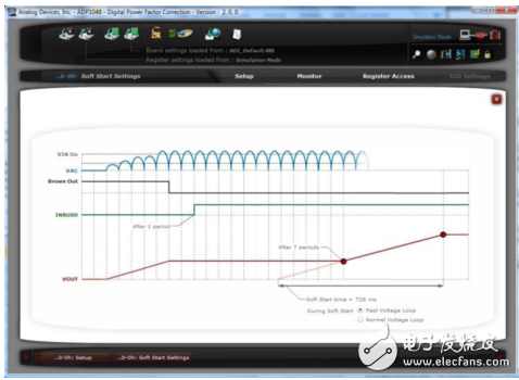
Figure 2. Graphical user interface simplification design
Benefits for motor control applications
The ADP1047/ADP1048 has two features that are especially useful in motor control applications. One is to detect system faults through precision power monitoring, and the other is to instantly adjust the PFC output voltage capability. Depending on the motor drive state, the voltage can be adjusted to increase efficiency without compromising performance. These “smart voltage†settings can be used when the motor is halted or operating at ultra low power. Figure 3 shows the PFC schematic contained in the motor control architecture.
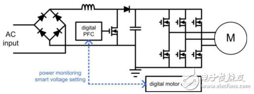
Figure 3. Motor Control Application
PFC is easy to use
Implementing a digital PFC solution does not necessarily require a difficult learning curve if a suitable controller IC and appropriate support software are used. This implementation is extremely valuable for dynamic applications such as motor control.
5V Wall Charger are wall plug adapters with 5V output, which are popularly used for tablets and mobile phones etc.
When you buy the Wall Mount Adapter, you should choose right plug. Besides, you should see the output current and dc plug size according to your device, the normal dc plug size are 2.5*0.7, 3.5*1.5, 5.5*2.5, 5.5*2.1, mini USB and MICRO USB etc.
For Yidashun's wall Power Adapter charger, there are different plugs for choose like: EU plug, US plug, UK plug, Australia plug, Argentina plug and Brazil plug and so on, which used in different countries.
Yidahsun's wall charger is with smart IC to protect your device with over current protection, over load protection, short circuit protection, over heat protection.


5V Wall Charger,5V USB Wall Charger,5V Portable Wall Charger,5V Wall Mount Adapter
Shenzhen Yidashun Technology Co., Ltd. , https://www.ydsadapter.com