LEDs are widely used in the industry because of their wide application and reasonable price. Whether it is a festive decorative lamp or a variety of lamps used in the home, LED driving circuits are used. Because of its reduced energy consumption, it can work stably for a long time. Today I will introduce the LED lighting driver circuit from a practical LED circuit.
Light-emitting diodes (LEDs) have become an alternative to today's lighting technology due to their high efficiency, energy saving, long life and environmental protection, and are gradually being applied to lighting. A key factor driving attention to LED lighting technology is that it greatly reduces energy consumption and enables long-term, reliable work.
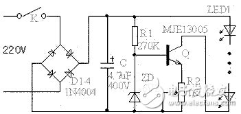
This article starts with a circuit using a constant current source. The main component transistor in this circuit requires a high-power tube with a withstand voltage of 400V or more and a power of 10W or more, such as MJE13003, MJE13005, etc., and a heat sink is required. The filter capacitor C has a capacity of 4.7uF and a withstand voltage of 400V or more. The current of the arc tube is determined by the R2 adjustment. For the convenience of adjustment, the variable resistor can be adjusted and then replaced with a fixed resistor of the same resistance. This circuit can be equipped with an arc tube. The number is less than a dozen, and the maximum can reach more than 90. Although the cost is increased, the effect is much better than that of the resistor-only current circuit. Even if the voltage fluctuates greatly, the circuit can keep the current constant. This is very advantageous for the life of the arc tube, and the current in this range can be kept substantially constant. The number of light-emitting tubes used in this circuit is not too small, and the less the efficiency, the lower the efficiency. The total power consumption of this circuit is about 6W.
Here, I will tell you about the LED adoption and connection method or the serial connection method?
LEDs are connected in series or in series, and should be determined mainly according to the form and requirements of the power box circuit.
With a series connection circuit, when one of the LEDs is open, the entire string of LEDs is not bright; but when one of the LEDs is shorted, the other LEDs are still bright. With the circuit of the parallel connection method, when one of the LEDs is open, the other LEDs can be bright; but when one of the LEDs is short-circuited, the power of the entire circuit will be short-circuited, so that not only other LEDs can not work normally, and It is also possible to damage the power supply. Therefore, the circuit connected in series is more advantageous.
The parallel method only needs to apply a lower voltage across each LED, but a ballast resistor or current source is needed to ensure that the brightness of each LED is consistent. If the magnitude of the bias current flowing through each LED is different, their brightness is also different, resulting in uneven brightness of the entire light source. However, using ballast resistors or current sources to ensure consistent LED brightness will shorten battery life. The series connection method is very good in ensuring the consistency of the current flowing through each LED, but the power supply voltage is required to be high. When the LED adopts the parallel connection method, since the total current of the circuit is the sum of the respective LED currents, the power supply is required to supply a sufficiently large current.
In fact, in parallel, parallel or series connection have their advantages and disadvantages. You need to consider many factors in practical terms. In practical applications, LED arrays formed in series and parallel are often used, which can overcome or reduce the above-mentioned single LED disconnection or short circuit, causing the entire string of LEDs to be off or affecting the entire circuit and power supply. The so-called series-parallel connection is to form a branch with a small number of LEDs in series and then a series of ballast resistors, and then several branches are connected in parallel to form a "branch group". In addition, it can also adopt the serial-parallel string form, that is, on the basis of the formed "branch group", a plurality of "branch groups" are connected in series to form the entire lamp circuit, and this connection not only reduces the failure of one LED. The influence surface, and the resistance of the ballast is reduced to zero, and several high-power resistors are turned into dozens of small-power resistors, which are changed from centralized installation to distributed installation, which not only facilitates heat dissipation but also designs the lamps. compact.
First of all, we must consider the power drive of any circuit. Usually, the LED is driven by a dedicated constant current source or a driver chip, which is easily limited by factors such as volume and cost. The most economical and practical method is to use a capacitor buck power supply. It uses it to drive low-power LEDs, has the advantages of not being short-circuited by load, simple circuit, etc., and a circuit can drive 1 to 70 low-power LEDs (however, the current impact when starting this power circuit, especially frequent startup, will give LED Damage is caused. Of course, proper protection can be used to avoid this impact. In this regard, ON Semiconductor's NUD4700 LED shunt protection solution can be used. When the LED is working normally, the leakage current is only nearly 100 μA; In transient or surge conditions, the LED will open, and the shunt channel in which the NUD4700 shunt protector is activated will have a voltage drop of only 1.0 V, minimizing the impact on the circuit. Designed for use in 1 W LEDs (rated at 350 mA @ 3 V) in a space-saving, small package, it supports operation greater than 1 A if properly handled.
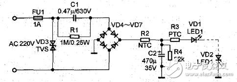
Typical circuit of capacitor buck power supply
Check the driver circuit, carefully check whether the circuit is connected according to the circuit diagram. Pay special attention to check the rectifier bridge (the long pin is the positive output, the diagonal is the negative output, the other two are the AC input) or the rectifier diode and the Zener diode. Whether the polarity is correct (the end with the black or white line printed is the negative pole), and whether the three electrodes of the transistor or the voltage-stabilized integrated circuit are checked for misconnection.
C1 is a step-down capacitor (using a metallized polypropylene capacitor) and R1 provides a discharge loop for C1. Capacitor C1 provides a constant operating current for the entire circuit. Capacitor C2 is an electrolytic capacitor, and its withstand voltage depends on the number of LEDs connected in series (about 1.5 times its total voltage). Its main function is to suppress voltage abrupt changes caused by energization moments, thereby reducing voltage shock. The impact on LED life. R4 is the bleeder resistor of capacitor C2, and its resistance should be increased as the number of LEDs increases.
Since the capacitor step-down power supply is a non-isolated power supply, a large current is generated at the moment of power-on, which is called a surge current. In addition, due to the influence of the external environment (such as lightning strikes), the grid system will invade various surge signals, and some surges will cause LED damage. Therefore, to provide thermistor protection, this is mainly a negative temperature coefficient thermistor protection (NTC thermistor, NTC is the abbreviation of NegaTve Temperature Coefficient) and positive temperature coefficient thermistor protection (PTC (PosiTIve Temperature Coefficient)) and then Transient Voltage Suppressor (TVS)
The negative temperature coefficient means a negative temperature coefficient, which refers to a semiconductor material or component with a large negative temperature coefficient. The simplest and most effective way to limit the inrush current is to connect an NTC thermistor in series with the line input.
The positive temperature coefficient current causes the temperature to rise after passing through the PTC thermistor, that is, the temperature of the heating element rises. When the temperature exceeds the Curie point, the resistance increases, thereby limiting the current increase, and thus the current decreases, the temperature of the element decreases, and the resistance value The reduction increases the circuit current, and the component temperature rises again and again.
Transient voltage suppressors are primarily used for fast overvoltage protection of circuit components. When the two poles of the TVS tube are subjected to reverse transient high-energy shock, it can change the high impedance between the two poles into a very low impedance at a speed of the order of 10-12s, absorb high-energy surges, and clamp the voltage between the two poles. Located at a predetermined value, the components in the protection circuit are protected from the impact of various surge pulses. (If you still have questions about the protection circuit, you can contact the author of this article Xiao Yingquan or contact QQ)
LEDs are increasingly favored by the industry, and research on its basic circuits is expected to be on a higher level. LEDs are more energy-efficient and more reliable in terms of reliability and stability. Then there will be a large application market in the future.
The Foxboro® Programmable Automation Controller (PAC) System is a high-performance automation controller and I/O subsystem integrated with easy-to-use Wonderware ® software. Foxboro PAC hardware marries high performance, reliability and high I/O density with cost-effective redundancy options. The process modules and I/O system form the basis of a complete distributed control and recording environment capable of continuous analog, logic and sequential control combined with secure data recording at point of measurement; all designed to maximize return on investment (ROI). Because it is engineered with some of the most advanced, yet proven technologies available, the Foxboro PAC system is very powerful, yet so simple to use.
FOXBORO Cards: I / A Series system, FBM (input / output modules) sequential control, ladder logic control, accident recall processing, digital-to-analog conversion, input / output signal processing, data communication and processing.

Foxboro Cards,Foxboro Dcs Card,Foxboro Dcs Card Module,Foxboro Fbm202 Interface Module
Xiamen The Anaswers Trade Co,.LTD , https://www.answersplc.com