Design of active UHF RFID system based on nRF9E5
Radio frequency identification (Radio Frequency IdenTIficaTIon, RFID) technology is a non-contact automatic identification technology using wireless radio frequency communication. Compared with the currently widely used barcode technology, RFID has large capacity, long recognition distance, strong penetration ability, Strong anti-fouling characteristics.
RFID technology has developed more maturely and obtained large-scale commercial use, but UHF RFID technology is relatively lagging behind. This article analyzes the functional characteristics of the radio frequency chip nRF9E5, and uses it in the RFID system, designed a set of active ultra high frequency (UHF) RFID system.
Selection of RF chip
At present, the more mature RFID systems are mainly 125kHz and 13.56MHz systems, and there are more corresponding RFID special chips, mainly including TI's S6700 series and NXP's MIFARE series. However, there are very few dedicated chips for UHF RFID. Although TI and NXP claim to have mass-produced RFID chips that comply with Gen2, they have not been able to put them into mass production due to various factors. In addition, in order to meet the user's requirements for long recognition distance, it is generally necessary to use an active UHF RFID system, and the current dedicated chip for active UHF RFID is even harder to find. Therefore, we need to find a low-cost radio frequency chip suitable for UHF RFID and easy to develop, to design an active UHF RFID system
With the development of the integrated circuit industry, 8051 cores have been integrated into various system-on-chips (SoCs). These SoCs have more functions, faster speed, smaller size and power consumption, and can continue to use 8051 MCUs. The various application software resources accumulated over the past decades have a broad space for development. Many internationally renowned companies, such as TI, ATMEL, Chipcon, Nordic, etc., have launched various new-generation short-range wireless communication chips compatible with 8051 core. Chipcon was acquired by TI in early 2006. Through analysis and comparison, it is found that both Chipcon's CC1010 and Nordic's nRF9E5 can be used in UHF RFID systems, while nRF9E5 is smaller in size, lower in cost, and has some unique functions.
nRF9E5 function analysis
â— Structural composition
The embedded 8051 compatible nRF9E5 microcontroller, RF transceiver and 4-channel 10-bit A / D converter, its functional structure is shown in Figure 1.
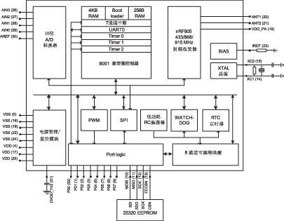
Figure 1 nRF9E5 functional structure block diagram
The on-chip microcontroller of nRF9E5 is compatible with the standard 8051, and the instruction timing is slightly different from the standard 8051. The interrupt controller supports 5 extended interrupt sources: ADC interrupt, SPI interrupt, wakeup interrupt and two wireless transceiver interrupts. In addition, two data pointers have been expanded to make it easier to access data from off-chip RAM.
The nRF9E5 built-in transceiver has the same function as the single-chip RF transceiver nRF905, and can communicate with the microcontroller through the on-chip MCU parallel port or SPI port. The transceiver consists of a frequency synthesizer, power amplifier, modulator and receiving unit. The output power, channel and other RF parameters can be controlled by programming the special function register RADIO. In the transmit mode (TX), the minimum operating current is only 9mA (output power -10dBm), the operating current in the receive (RX) mode is 12.5mA, and the operating current in the power-down mode is only 2.5μA. It can be seen that the power consumption of nRF9E5 is very low, which is more suitable for application in active RFID systems to extend battery life.
â— Carrier detection
Carrier detection is a major feature of nRF9E5. In the ShockBurst receiving mode, when a radio frequency carrier appears in the working channel, the carrier detection pin (CD) is set high. That is to say, when the transceiver is ready to send data, it first enters the receiving mode and detects whether the working channel can send data (whether the channel is idle), which is a simple pre-transmission listening protocol. The carrier detection standard is generally 5dB lower than the sensitivity. For example, the sensitivity is -100dBm, and the carrier detection function detects carriers as low as -105dBm. This feature avoids collisions between data packets of different transmitters at the same operating frequency, and is very helpful for solving collision problems in RFID systems.
â— ShockBurst working mode
nRF9E5 uses Nordic's ShockBurst technology (automatically handles prefix, address and CRC) to achieve low-speed data input and high-speed data output, thereby reducing the average power consumption of the system. In the ShockBurst receiving mode, when a radio frequency packet with a valid address is received, the address matching register (AM) and the data ready register (DR) notify the on-chip MCU to read the data. In the ShockBurst sending mode, nRF905 automatically adds the prefix and CRC check code to the data to be sent. When the data is sent, the data ready register (DR) will notify the MCU that the data has been processed. When the system does not send and receive tasks, it will enter idle mode. ShockBurst technology reduces MCU memory requirements and shortens software development time.
Active UHF RFID system design
â— Hardware design
Electronic tags and readers are the most important hardware components in RFID systems. The nRF9E5 chip is used in active UHF RFID systems (operating frequency is 433MHz) to design active electronic tag circuits and reader block diagrams.
The electronic tags in the active RFID system have their own batteries and can actively send signals, unlike passive tags that require the activation of radio wave energy emitted by the reader to work. nRF9E5 has the characteristics of small size, low power consumption, superior power management mode and few peripheral devices, which is very suitable for active electronic tags

Figure 2 Basic block diagram of active tags
Figure 2 is a basic block diagram of an active tag, where the battery can use a common 3V button battery, Figure 3 is a schematic diagram of the RF transceiver circuit, ANT1 and ANT2 are antenna connection pins, using a PCB loop differential antenna can further reduce the tag volume of. 25320 is EEPROM. After nRF9E5 is powered on, the system copies the program code in 25320 to the 4KB RAM of nRF9E5 according to the boot program. The operating frequency of the crystal oscillator is 16MHz. In order to obtain an accurate internal bias voltage, a resistor with a resistance of 22kΩ and an error of 1% is usually connected between the pin IREF and ground.
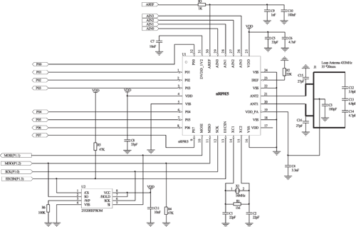
Figure 3 RF transceiver circuit diagram
The task of the RFID reader is to control the radio frequency module to transmit a read signal to the tag and receive the tag's response, decode the tag's object identification information, and transmit the object identification information along with other relevant information on the tag to the host for processing. The basic structure of the reader is shown in Figure 4. The reader can be simplified into two basic functional blocks, a control system and a radio frequency module composed of radio frequency transceivers.
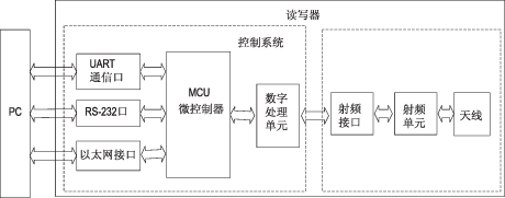
Figure 4 Basic structure of the reader
The control system is usually implemented with ASIC components and microprocessors. The main functions are: to communicate with the application system software and execute the action commands sent from the application system software; the communication process between the control and the label; the signal encoding and decoding; execution Anti-collision algorithm; encrypt and decrypt the data transmitted between the reader and the tag; verify the identity between the reader and the tag. The main functions of the radio frequency module are: generating high-frequency transmission energy; modulating the transmission signal for transmitting data to the label; receiving and demodulating the radio frequency signal from the label.
In the designed system, the RF module in the reader is similar to the RF module circuit in the active tag, but in order to transmit the RF signal more efficiently, a single-ended 50Ω impedance antenna is used, and the chip antenna needs to be connected to the pin Add a matching network between the antenna and the antenna, as shown in Figure 5.
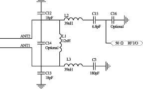
Figure 5 RF matching network
The microcontroller in the control system can use high-performance single-chip microcomputer or ARM processor, the digital processing unit can be designed using DSP or FPGA, and the RS-232 serial port and Ethernet port provide more interface options for PC. These A lot of content has done a lot of research in the literature, and it will not be detailed here. In this system, Samsung's ARM9 S3C2440A is used as the microcontroller, and Xilinx Spartan-3E series FPGA XC3S500E is used as the digital processing unit.
â— Communication protocol standard
Since the communication between the reader and the tag may be interfered by other data terminals or the external environment and cause errors, a communication protocol is required to ensure the reliability of data transmission. The protocol format of nRF9E5 is shown in Table 1, where the prefix is ​​the data header, the device address includes the reader address and tag address, and the CRC check code can be 8 or 16 bits.
Many companies producing RFID products currently use their own protocol standards, and there is no uniform standard internationally. In terms of development trends, for ultra high frequency (UHF) RFID systems, ISO / IEC 18000-7 (for 433MHz active RFID systems) and EPCglobal Class1 Gen2 (for 860MHz ~ 960MHz passive RFID systems) protocol standards are expected to become unified International standards. The communication protocol of RFID system designed in this paper is based on ISO / IEC 18000-7 protocol standard. The communication data format of the reader to the tag is shown in Table 2. Among them, the user ID, tag ID and parameters are optional, and it is determined by the command type. See Table 3 for the communication data format of the tag-to-reader broadcast response. 


â— Software configuration
In the software design of the entire system, the transmission of radio frequency data is the most important part. First, the nRF9E5 needs to be initialized and configured. This can be done by setting the RF configuration register. The configuration includes the operating frequency, output power, automatic retransmission function, check code length, etc. Part of the code is as follows.
#define HFREQ_PLL 0 // 0 = 433MHz, 1 = 868 / 915MHz
#define PA_PWR 3 // 0 = minimum power, ..., 3 = maximum power
#define CRC_MODE 1 // 0 = 8-bit check code, 1 = 16-bit check code ...
The processes of wireless data transmission and reception are shown in Figure 6 and Figure 7, respectively. In the figure, TRX_CE is the transmit and receive enable register bit, DR is the data ready register bit, AM is the address matching register bit, and AUTO_RETRAN is the automatic retransmission register bit. ShockBurst working mode has been introduced in the previous article.

Figure 6 nRF9E5 send data flow
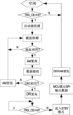
Figure 7 nRF9E5 receiving data flow
The problem of anti-collision of this system has not been completely solved. In practical applications, it needs to be considered. In addition to the carrier detection function of nRF9E5 mentioned above, a special anti-collision algorithm is also required. At present, the most used methods are ALOHA method and binary tree search algorithm, and a series of algorithms improved and developed from them, see references 5-7.
Conclusion
nRF9E5 is one of the single-chip RF transceiver chips with the fewest external components. It covers the international ISM frequency band and has many excellent characteristics. It is suitable for building various wireless data transmission communication platforms. It is used in RFID systems in this article. , Designed a set of active UHF RFID system, experimental tests show that the maximum communication distance is close to 100 meters, and the effective recognition distance exceeds 20 meters. This is only a preliminary attempt, more work needs in-depth study, and the practicality of the system needs to be further verified.
General Electric (GE) is an American multinational conglomerate incorporated in New Yorkand headquartered in Boston, Massachusetts. As of 2016, the company operates through the following segments: aviation, current, digital, energy connections, global research, healthcare, lighting, oil and gas, power, renewable energy, transportation, and capital which cater to the needs of financial services, medical devices, life sciences, pharmaceutical, automotive, software development and engineering industries.
General Electric Fanuc: modules, cards, drives and other spare parts, IC693, IC695, IC697 IC698 series.
General Electric Fanuc
General Electric Fanuc,Ge Industries Controller,Ge Intelligent Platforms,Removable Eeprom Memory Card
Xiamen The Anaswers Trade Co,.LTD , https://www.answersplc.com