Important Information
Mobile communication systems have evolved significantly over the years, starting from the first generation (1G) and now reaching the fourth generation (4G). The fifth generation (5G) is currently being standardized and is expected to be commercially available by 2020. This paper provides a detailed overview of the base station architectures used in 2G, 3G, 4G, and 5G systems.
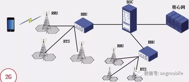
1. 2G
The 2G system was based on a three-tier network architecture: BTS (Base Transceiver Station), BSC (Base Station Controller), and the core network. The core network included both the Circuit Switched (CS) domain and the Packet Switched (PS) domain. Initially, 2G used an integrated base station design, where the antenna was mounted on a tower and the rest of the equipment was located in an adjacent room. This setup required a dedicated machine room under each tower, which made construction costly and time-consuming. It also limited scalability and flexibility for future expansion.

Later, this evolved into a distributed base station architecture, where the BTS was split into RRUs (Radio Remote Units) and BBUs (Baseband Units). The RRU handled RF-related functions, including IF modules, transceivers, power amplifiers, and filters. The BBU managed baseband processing and protocol stack tasks. The RRU was placed on the tower, while the BBU was in the indoor equipment room. A fiber connection linked the two, allowing one BBU to manage multiple RRUs (typically 3–4).
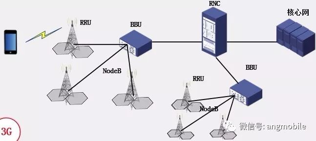
2. 3G
To reduce costs during 3G network deployment, the architecture closely followed that of 2G. It also used a three-tier structure: NodeB–RNC–core network. The core network still had both CS and PS domains. During the 3G era, the distributed base station model became more common, with NodeB divided into BBUs and RRUs, similar to the 2G approach.
3. 4G
With the arrival of 4G, the base station architecture underwent significant changes. To reduce latency, 4G introduced a flat network structure, reducing the original three-tier system to two levels: eNodeB–core network. Part of the RNC’s functions were moved to the eNodeB or the core network. The 4G core network only supported the PS domain. China Mobile’s C-RAN (Cloud Radio Access Network) architecture was also adopted, centralizing and virtualizing BBU functions. This allowed one BBU to connect up to 100 RRUs, improving efficiency and reducing deployment costs.
Unlike traditional setups, C-RAN decouples the RRU and BBU, enabling dynamic resource allocation. Each RRU can be managed by a virtual baseband unit, which draws processing power from a shared pool using real-time virtualization technology.
![]()
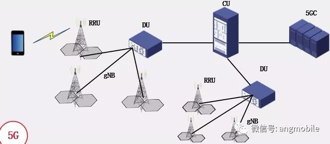
4. 5G
To enhance flexibility, 5G introduced a three-layer architecture: DU (Distribution Unit), CU (Centralized Unit), and the 5G Core (5GC). The DU and CU together form a gNB, and each CU can connect to multiple DUs. There are various functional splits between the CU and DU, allowing the system to adapt to different use cases and performance requirements. This modular approach supports a wide range of applications, from high-speed mobile broadband to ultra-low-latency services like autonomous driving and remote surgery.
Three Phase Online UPS,Tower Online UPS,Rack Mount Online UPS,Isolation Transformer
Shenzhen Unitronic Power System Co., Ltd , https://www.unitronicpower.com