Important Information
Mobile communication systems have evolved significantly over the years, starting from the first generation (1G) and progressing to the fourth generation (4G). The fifth generation (5G) is now being standardized and is expected to become commercially available by 2020. This paper provides an overview of the base station architectures used in 2G, 3G, 4G, and 5G systems.
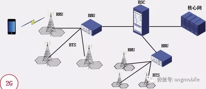
1. 2G
The 2G communication system originally used a three-tier network architecture: Base Transceiver Station (BTS), Base Station Controller (BSC), and the core network. The core network included both the Circuit Switched (CS) domain and the Packet Switched (PS) domain. Initially, 2G base stations were integrated, with the antenna mounted on a tower and the rest of the equipment located in a nearby room. This setup required a dedicated machine room under each tower, which was costly and time-consuming to build. It also made it difficult to scale the network efficiently.

Later, the architecture evolved into a distributed model, where the BTS was split into Remote Radio Units (RRUs) and Baseband Units (BBUs). The RRU handled RF functions such as signal processing, power amplification, and filtering, while the BBU managed baseband processing and protocol stack tasks. The RRU was placed on the tower, and the BBU was located in the indoor equipment room. A fiber connection linked the two, allowing one BBU to support multiple RRUs (typically 3–4).
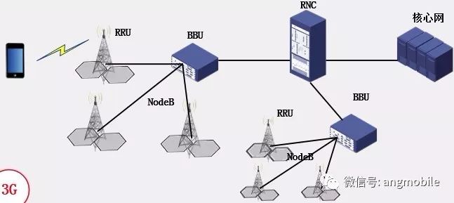
2. 3G
To reduce costs during 3G network deployment, the architecture largely followed that of 2G. It also used a three-tier structure: NodeB, Radio Network Controller (RNC), and the core network. Like 2G, the 3G core network supported both CS and PS domains. During the 3G era, the distributed base station architecture became more common, with NodeB divided into BBU and RRU components.
3. 4G
With the arrival of 4G, the base station architecture underwent significant changes. To reduce latency, 4G introduced a flatter network structure, reducing the number of layers from three to two: eNodeB and the core network. Some of the RNC's functions were moved to the eNodeB or the core network. The 4G core network only included the PS domain. China Mobile’s C-RAN (Cloud Radio Access Network) architecture was also introduced, centralizing and virtualizing BBU functions. This allowed a single BBU to connect to 10–100 RRUs, significantly reducing deployment time and cost.
In contrast to traditional distributed models, C-RAN allows for more flexible resource allocation. Each RRU is not tied to a specific BBU but instead connects to a virtual baseband station. This station uses real-time virtualization technology to allocate processing power from a pool of BBUs, making the system more scalable and efficient.
![]()
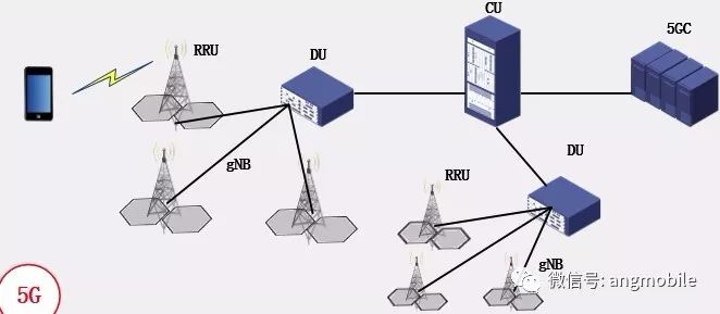
4. 5G
To enhance flexibility and performance, 5G adopts a three-layer architecture: Distributed Unit (DU), Centralized Unit (CU), and the 5G Core (5GC). The DU and CU together form a gNB, with each CU potentially connected to multiple DUs. There are various functional splitting options between the CU and DU, allowing the system to adapt to different use cases and requirements, such as high-speed data transfer, low-latency communication, and massive IoT connectivity.
Power Distribution Unit,Smart Power Distribution Unit,Cabinet power distribution socket,OUTLET SWITCHED PDU,Power PDU
Shenzhen Unitronic Power System Co., Ltd , https://www.unitronicpower.com