To address the cost and efficiency challenges associated with software updates in industrial remote control systems, this paper proposes a remote loading method for DSP programs based on Ethernet communication. Focusing on the structure and boot process of a DSP system using the TMS320C6670 as its core, the method leverages the BOOTP protocol over Ethernet UDP to enable efficient and flexible program loading. Practical implementation has demonstrated that this technique is reliable and convenient, significantly improving the debugging and updating processes of remote control systems.
Introduction
With the rapid development of science and technology, network communication and DSP technologies have advanced significantly. Many intelligent instruments and industrial remote control devices now connect to the Internet, enabling smart management and control. Among these devices, many are based on DSP technology, and the program booting process is a critical aspect. Traditionally, program loading for DSP devices is done via hardware emulators, which can be inconvenient for maintenance and updates in real-world industrial settings. As a result, network-based software updates have emerged as a more efficient and practical solution.
This paper introduces the fundamental principles of DSP program loading. Taking TI's multi-core DSP TMS320C6670 as an example, we implement a program loading technology based on the Ethernet BOOTP protocol. This approach enables dynamic program loading over the network, greatly improving software update efficiency and flexibility.
1. Principle
In this setup, a traditional PC acts as the download server, while the TMS320C6670-based DSP device functions as the client. Upon startup, the client does not possess any network information and relies on TCP/IP protocols such as IP, UDP, and BOOTP to obtain necessary details. These protocols facilitate the transmission of information, allowing the client to retrieve the boot program through UDP and execute it accordingly.
1.1 IP Protocol and UDP Protocol
The IP (Internet Protocol) operates at the network layer of the TCP/IP stack, while UDP (User Datagram Protocol) is a connectionless transport layer protocol. In local area networks where reliability is high, UDP is often used due to its low overhead compared to the full TCP/IP stack.
1.2 BOOTP Protocol
When a client starts, it needs to obtain three key pieces of information from the network: its own IP address, the IP address of the download server, and the name of the program to be downloaded. The BOOTP (BOOTstrapping Protocol) allows diskless machines to retrieve all necessary booting information. Since the client initially lacks both its own IP address and the server’s, it must broadcast a BOOTP request. Once the server receives the request, it looks up the corresponding entry in the database and sends a response, which the client then processes to begin execution.
BOOTP transactions involve a single request and response. If the transaction fails due to server downtime or network issues, the client will retransmit the request every three seconds. In cases where multiple responses are received, the client typically accepts the first one and discards the rest.
1.3 BOOTP Packet Format
The format of a BOOTP packet is illustrated in Figure 1. It includes fields such as opcode, hardware address type, hardware address length, transaction ID, client IP address, server IP address, and optional parameters like the boot file name and standard options.

1.4 Ethernet Packet Format
The Ethernet request packet format is shown in Figure 2. It contains destination and source MAC addresses, IPv4 header, and UDP segments. The Ethernet boot package format is also illustrated in Figure 3, showing how data is structured for network booting.


2. Hardware Design
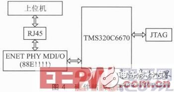
The system uses the TMS320C6670 multi-core DSP as the main controller, which includes a built-in Gigabit network coprocessor. This reduces the need for additional peripheral components, requiring only a physical layer chip. A block diagram of the system is presented in Figure 4.
3. Download Implementation Process
On the client side, when the hardware resets, the DIP switches SW3, SW4, SW5, and SW6 on the development board are configured to set the TMS320C6670 into Ethernet boot mode. The RBL (ROM BootLoader) initializes SerDes, SGMII, and PASS to prepare for receiving boot packets. It then sends an Ethernet request packet every 3 seconds.
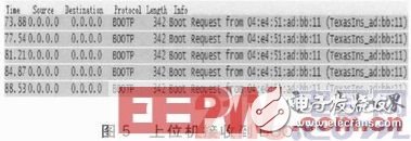
On the server side, a PC running Wireshark captures the Ethernet request packets and responds accordingly. As shown in Figure 5, the BOOTP packet is broadcast every 3 seconds.
5.08mm Pitch
5.08mm Pitch
HuiZhou Antenk Electronics Co., LTD , https://www.atkconn.com