1. Signal lines and power lines must be kept separate. When using analog signals to remotely control an inverter, it's essential to minimize interference from the inverter and other devices. Ensure that the signal line is separated from the inverter's main circuit and control loop. Maintain a distance of at least 30cm between them. Even inside the control cabinet, follow this wiring rule. The length of the control loop between the signal and the inverter should not exceed 50 meters.
2. Signal and power lines should be placed in different metal conduits or pipes. Since the two Fuji inverters in the water system are located 30m and 20m away from the control cabinet respectively, the signal lines connecting the PLC and inverter are not installed in metal conduits, making them susceptible to interference. Additionally, since the inverters don't have built-in reactors, their input and output stages can cause strong external interference. Therefore, the signal lines should always be routed through metal conduits or hoses up to the inverter’s control terminals to ensure complete isolation from the power lines.
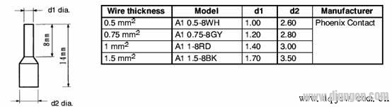
3. For analog control signal lines, use double-stranded shielded cables with a cross-sectional area of 0.5 to 2 mm². When stripping the cable, keep the exposed part as short as possible (5–7 mm). After stripping, wrap the shield with insulating tape to prevent it from touching other equipment and causing interference.
4. To improve wiring simplicity and reliability, it's recommended to use crimping bar terminals on the signal lines. The crimp terminal selection is shown below:
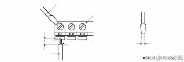
5. If crimping terminals are not available, take extra care during wiring. Refer to the following diagram for proper connections:
7. The inverter’s grounding should be separate from the PLC control circuit. If separate grounding isn’t possible, float the control circuit ground to reduce interference from the inverter. However, the inverter must still be reliably grounded. In the control system, it’s recommended to float both ends of the shielded signal line for analog signals. Also, since the PLC and inverter share a common ground, consider grounding the PLC separately or isolating it when possible.
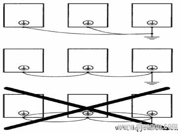
8. Inverter Grounding: For 400V class inverters, use type C grounding with a resistance of 10 ohms or less. Avoid sharing the grounding wire with welding machines or other high-power equipment. The grounding wire size should comply with electrical standards. For example, a 35kW inverter recommends a 22 mm² grounding wire, while an 87kW inverter suggests a 50 mm² wire. Keep the ground wire as short as possible to avoid unstable potential at the grounding point. When multiple inverters are used, do not loop the ground wire. Refer to the following diagram:
9. Wiring Distance Between Inverter and Motor: If the distance between the inverter and motor is long, the high-order harmonic leakage current from the cable may negatively affect the inverter and other equipment. To reduce interference, adjust the inverter’s carrier frequency accordingly. Refer to the table below:
Wiring distance: 50m or less – Carrier frequency: 15kHz or less 100m or less – Carrier frequency: 10kHz or less 100m or more – Carrier frequency: 5kHz or less
PP PE Rigid Plastic Pelletizing Line
Pp Pe Rigid Plastic Pelletizing Line,Pelletizing Line For Pp Pe Rigid Plastic,Pp Pe Rigid Plastic Pelletizing Machine,Pp Pe Rigid Plastic Pelletizing System
Zhejiang IET Intelligent Equipment Manufacturing Co.,Ltd , https://www.ietmachinery.com