PoE transmits power through Ethernet connection. In the PoE power supply network, the power supply device (PSE) provides power, and the Ethernet network generates an output voltage of 44 to 57 V. On the other end of the Ethernet connection, the power receiving device (PD) consumes the power. Although a higher power Ethernet power supply standard is currently being defined, the power available to the powered device is now limited to about 13W in the case of a single Ethernet connection. Unfortunately, such power is often insufficient to support complex applications, so some high-power powered-end devices require the power of multiple ports to be converted to usable voltage and isolated from the 48V input voltage. There are currently a number of techniques that provide isolated power conversion from multiple input sources.
Power over Ethernet (PoE) has become a common concept and has been applied to products such as VoIP, security monitoring systems, and cash registers.
Falling method
One technique commonly used in DC/DC parallel power supplies is the so-called descent method. If the output voltage of the parallel power supply is reduced and the load current is increased, the parallel power supply will share the current. This approach eliminates the need for communication between power supplies and does not result in a single false failure, and requires very few additional parts. If current mode control is used, it is only necessary to limit the DC gain of the control loop to produce a drop in output voltage proportional to the increase or decrease of the load current.
Unfortunately, the way to reduce sharing is not very precise. If these power supplies are connected in parallel, the output voltage will generally be regulated by the highest output power supply in the absence of load. If the power supply is diode-regulated as shown in Figure 1, the lowest output power supply will not output any current. As the load current increases, the output voltage begins to drop, and all current is supplied by the power supply with the highest output voltage until the output value drops to 5.25V, after which the second highest power supply begins to supply current. With the worst-case tolerances assumed above, the first power supply already provides about 70% of the output power before the lowest output voltage source begins to function. This is not ideal because it is not reliable enough, but under certain conditions. May be acceptable. As the load current increases further, the first power supply may reach the limit, after which the remaining two power supplies are responsible for increasing the current to achieve full power operation.
A power supply architecture with synchronous rectification allows the power supply or sinks the output current, which can cause significant problems for this control method. In extreme cases, a single power supply may attempt to regulate the high current and low current terminals. If this happens when there is no load, some power supplies will supply current to the output, while some will draw current from the output, which will get power from one source and then feed the second to the second. Power is transferred to the load; therefore it is recommended to disable synchronous rectification at zero amps.
Interlaced return
Another technique for balancing multiple input powers is the interleaving method. The interleaving method, like the descent method, uses different power levels for each input and supplies the power to a common output. The difference from the descent method is that the interleaved power level (or phase) shares a common primary side controller, which can reduce the cost, and each power level can also be in the opposite phase (out of phase). ) Time synchronization. Synchronization reduces the chopping current of the output capacitor, so a smaller output filter can be used. In the interleaving method, all power inputs must share the same loop, so this method cannot be used in some applications.
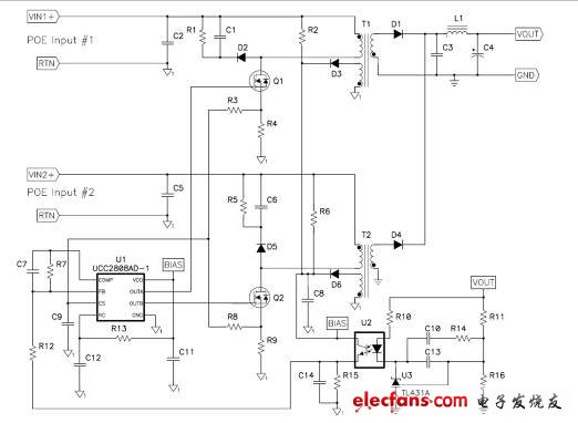
Figure 1: Push-pull controller drives interleaved flyback.
Many Pulse Width Modulation (PWM) controllers are specifically designed for interleaving. If only two phases are required, an interleaving method can be performed using a push-pull controller to significantly reduce cost. Figure 1 shows a two-phase interleaved flyback power supply using a push-pull controller like the UCC2808, which limits the duty cycle of each phase to 50% and reverses the phase of the two power stages by 180 degrees. Make the conversion. This push-pull controller uses peak current mode control to keep both phases close to the same peak current value. In discontinuous flyback, the output power of each phase is proportional to the square of the primary peak current, thus naturally balancing the power obtained by the two input sources. This technology can reduce the power gap between the two input sources to less than 5%. The switching delay of the primary MOS half-effect transistor (MOSFET) is the main cause of the imbalance, which is the worst when the two input voltages are not equal. The peak current limit provided by the controller limits the maximum power obtained by the two inputs, while the load cycle clamp limits the input current under undervoltage and failure conditions.
Use a secondary side load sharing controller to share power
The third way to share power between multiple inputs is through a secondary side load sharing chip. In this way, independent power supplies with remote sensing capabilities, regardless of the number, can share the same output. The load sharing chip is often shared with the power module. Please refer to the example in Figure 2. A shunt resistor is used to measure the current supplied by each converter. Because of the tolerance and parasitic impedance, one of the power supplies will supply more current, this power will be used as the main power supply, and the voltage will be set on the load sharing (LS) bus. The slave unit uses this load sharing bus voltage as the input reference to Control your own output current. If the slave unit is to be adjusted, a voltage can be injected into the remote sense conductor of the slave converter so that the output voltage of the load can be controlled from the main power source to maintain good load regulation. Using this master/slave mode results in very good current sharing accuracy, which is generally better than 3% at full load.
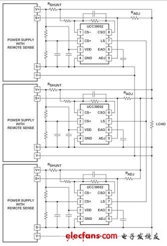
Figure 2: The load sharing controller can be connected in parallel with a separate power supply.
Since each parallel power supply requires a load sharing controller and external discrete components, the number and cost of components for this approach is slightly higher than the descent and interleaving methods. In addition, it is not recommended to use both the load sharing controller and the synchronous rectifier, as problems may occur when starting or adding or removing individual power supplies.
Master/slave isolation primary side current sharing
Another technique that can be used for parallel power supplies is to sense a primary current (main) and then compare it with another current (slave). Whether using optocouplers or current transformers, current information can be transferred between power supplies while maintaining isolation. Current transformers are the best choice because they can achieve good performance at the lowest cost. In addition, current transformers have good accuracy compared to optocouplers. The accuracy of the current transformer is determined by the turns ratio tolerance and the resistance tolerance. The former is better than 2%, and the latter is generally 1%. The accuracy of the optocoupler depends on the current conversion rate tolerance, and the best condition is 30%.
Summary of this article
The descent method is the easiest way and one of the least expensive ways, but the worst performance, but no single point of failure. In general, the best performing technology is the load sharing controller and the most expensive solution. Using a staggered primary controller or optocoupler/current transformer technology, a balance between cost and performance can be achieved. In addition, such as the use of synchronous rectifiers, the number of Ethernet power inputs, and whether the Ethernet power input needs to be isolated from each other, these additional factors need to be considered to determine which method should be used. Use the right technology for your application to get the maximum power from the Ethernet network.
We'd love to create a bespoke Neon LED Sign just for you!
Our signs are made to order. We can create anything your heart desires! Weddings, events, business signs, in your home - big, small - we can make it a reality!
MOQ: 1 piece only.
Neon Wedding Sign, Neon Party Sign, Neon Wedding Light
Shenzhen Oleda Technology Co.,Ltd , https://www.baiyangsign.com