Many applications for LED lighting require a wide dimming ratio. This can be achieved simply by an adjustable current source as shown below. A variety of different methods can be used to vary the current source and achieve a large LED current range. The main problem with this approach is that power dissipation can be quite high. A high enough voltage source V1 must be chosen to accommodate the maximum LED voltage drop and the required reserve space for the current source. LED manufacturers typically specify a maximum voltage above the average, thus forcing the designer to use a higher than desired input voltage. The use of multiple LEDs in series increases the voltage tolerance problem by a factor of two.
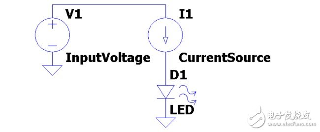
A simple LED driver with an adjustable current source
Another way to increase the dimming ratio is to use a pulse width modulation (PWM) signal to the LED to pulse-on and pulse-off it. If the pulse can be completed at a sufficiently high rate (usually a few hundred Hz), the pulsation is invisible to the human eye. This method can be used to expand the dimming ratio to 3000:1.
Although the pulsation is invisible to the human eye, it can be a problem for other applications. For example, the scanning rate of a digital video recorder will interact with the flashing of the LEDs, creating undesirable artifacts.
Hybrid solution with LT8614 Silent Switcher and LT3083 linear regulator
A potential technique allows the use of a rigorous simulation method to control the wide dimming ratio. It uses a hybrid approach in which a switching regulator maintains a constant voltage across an adjustable current source and places the LED voltage within a feedback loop so that the LED voltage changes to the LED current. No effect. The voltage across the current source does not have to support the LED voltage drop and its variation, so it can be optimized for the best choice of “power consumption versus dimming ratioâ€. The following example illustrates this concept with an example using the LT8614 as a voltage source and the LT3083 as the current source.
The LT8614 is a buck regulator with a Silent Switcher architecture designed to minimize EMI / EMC emissions and provide high efficiency up to 3MHz. Its monolithic structure is assembled in a 3mm x 4mm QFN package with an integrated power switch and all necessary circuitry, resulting in a positive PCB footprint solution. The LT3083 is a 3A low dropout linear regulator that can be used in parallel to increase output current or spread heat on surface mount boards. Designed for use as a precision current source and voltage follower, this new regulator is used in many applications that require high current, zero to zero regulation, and no heat sink.
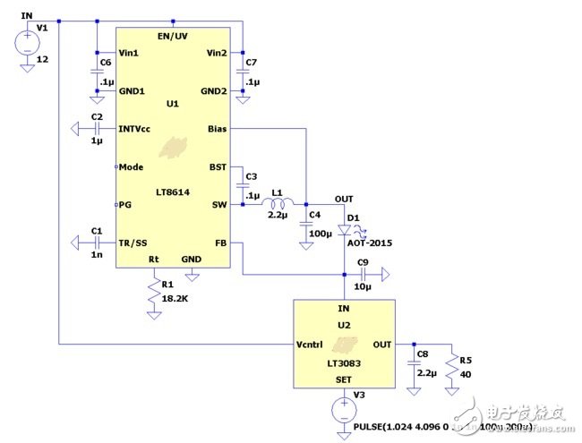
Hybrid LED driver with LT8614 voltage source and LT3083 current source
In this case a 12V input voltage is used and the LED current is varied from 0A to 3A through a 0V to 300mV signal applied to the SET terminal of the LT3083. The LT3083 OUT terminal follows the SET terminal, so a constant current flows through R5 (through IR5 = VSET/R5 below).
The current in the IN terminal of the LT3083 follows the current in the OUT terminal very accurately until it reaches a minimum load of approximately 500μA.
The LT3083 requires a worst case differential voltage of 510mV (from IN to OUT) and a differential pressure of 300mV (for R5 at maximum current). The LT8614 maintains the voltage on the IN terminal of the LT3083 to exactly 0.97V, which maintains the LT3083's power dissipation at an acceptable level, reaching a peak power of approximately 2.4W at 3A output current.
The LED negative is held at 0.97V by the LT3083, but due to the feedback action of the LT8614, the LED positive voltage will change to any desired voltage. More LEDs in series with D1 can be placed and the current will not change until the LT8614's dropout voltage is reached.
Hybrid solution with LT8614 Silent Switcher and LT6015 op amp
The LT3083 is an easy-to-use device that implements current source functionality, but as detailed above, the device has no minimum load requirements. In addition, there is a slight offset between the SET and OUT terminals, which is typically a few hundred microvolts, but can be as high as ±6mV over temperature. This offset sets a lower limit for the dimming ratio. If a larger dimming ratio is required, a discrete current sink with a low offset voltage op amp can be used. One such implementation uses the LT6015 precision op amp as the control element.
The LT6015 is a rail-to-rail input op amp with an input offset voltage trimmed to less than 50μV. The amplifier operates from a single supply and a separate supply (total voltages from 3V to 50V), each absorbing only 315μA. The LT6015's Over-The-Top® input stage is designed to provide extra protection in harsh environments.
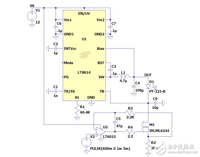
Hybrid LED driver with LT8614 voltage source and LT6015 current sink
The LT6015 has a maximum offset voltage of ±250μV over the entire temperature range, and the current source requires only a dropout voltage of approximately 100mV. This allows the full scale voltage to be increased to 600mV and a dimming ratio of approximately 1000:1.
software
LTspice
The LTspice IV is a powerful, fast and free simulation tool, schematic capture and waveform viewer that provides improvements and models for improving the simulation of switching regulators. Click here to download LTspice IV
To start the ready-to-run LTspice demo circuit for this device, follow these steps:
Step 1: If LTspice is not installed on your computer, please download and install LTspice IV
Step 2: After installing LTspice, click on the link below to start the simulation
LT8614/LT3083 Demo Circuit - Hybrid Wide Dimming RaTIo Linear LED Current Controller (3.4-42V to 41V @ 3A Max)
LT8614/LT6015 Demo Circuit - Hybrid Wide Dimming RaTIo Linear LED Current Controller (3.4-42V to 41V @ 3A Max)
Step 3: If the LTspice IV does not open automatically after clicking the link above, you can right click on the link and select "Save Target As". After saving the document to your computer, launch LTspice and open the demo circuit by selecting "Open" from the "File" menu.
DC Capacitor For Electric Furnace
DC Capacitor For Electric Furnace
DC Capacitor For Electric Furnace,DCMJ DC Filter Capacitors,DCMJ Pulse Capacitors,DCMJ DC Support Capacitors
YANGZHOU POSITIONING TECH CO., LTD. , https://www.yzpst.com