Ultraviolet communication has very good non-line-of-sight transmission and privacy. Traditional ultraviolet communication systems are too large to be practical. As a new communication means, UV communication has the most outstanding advantages: it is not easy to be detected and intercepted, and it can be used for non-line-of-sight communication by scattering. It is very suitable for short-distance anti-interference and occlusion communication environments.
Foreign countries began to study ultraviolet light communication in the 1960s, and completed many aspects of research from basic principles to practical systems. In 2000, GTE of the United States successfully developed a new concealed ultraviolet-light wireless simplex communication system based on mercury lamps for the US military. The communication rate of this system is 4.8Kb/s and the bit error rate can reach 106. In 2002, the US Department of Defense's Advanced Research Projects Agency (DARPA) launched the Semiconductor Ultraviolet Systems (SUVOS) program, whose core mission was to manufacture ultraviolet light-emitting diodes (UV LEDs). Under the impetus of the program, UV LEDs have been successfully developed and mass production has begun.
The University of California, Riverside and the Massachusetts Institute of Technology used UV LEDs to construct a simplex communication test system and studied the characteristics of the UV transmission channel.
Since 2000, the company has been tracking UV-light communication technology. Chongqing University, Beijing Institute of Technology, National Defense Science and Technology University and other units have completed the development of a prototype of UV-based simplex communication system with a transmission rate of up to 9.6Kb/s. But so far, the UV light source used in these systems in China is still a low-pressure mercury lamp or a xenon lamp, which is large in size and power consumption, and is difficult to be miniaturized and portable. Another outstanding problem is that these systems at home and abroad can only perform simplex communication, which limits the practicability of the system to some extent.
This paper studies and designs a duplex UV-based communication system based on UV LED, which can be used for two-way secure transmission of air and short-distance voice and data.
1. Characteristics of ultraviolet light communication
Ultraviolet communication has the following characteristics:
1. The wavelength is 200~280nm. This band is open and is not subject to the Radio Regulatory Commission and does not require frequency application when in use.
2. The ultraviolet light of 200~280nm belongs to the day blind segment. The sunlight of this wavelength is absorbed by atmospheric molecules and suspended particles, and the signal intensity decays exponentially. The energy when it reaches the surface is very weak. Therefore, the background noise of ultraviolet light communication is very small.
3. Due to the influence of atmospheric attenuation, ultraviolet light is suitable for short-range communication within 1km. After this range is exceeded, it will be difficult to detect, and it is unlikely to interfere and intercept it. Therefore, the confidentiality of ultraviolet communication is very high.
4. The ultraviolet light source illuminates the space of the receiver's field of view, and is scattered by the tiny particles in the atmosphere, scattered into the field of view of the receiver, and received by the receiver. Therefore, UV light can be used for non-line of sight communication (NLOS) and is suitable for use in occluded scenes.
Due to the above characteristics, the ultraviolet communication system can be widely used in tactical mobile communication and secure communication.
2. Design of duplex UV communication system
The current ultraviolet communication system is one-way communication, and the modulation method uses a conventional OOK (on-off) and PPM (pulse position modulation) mode. If you want to achieve two-way communication, one solution is to adopt frequency division multiplexing. The transmitting and receiving parties occupy a different wavelength in the range of 200~280nm. The other solution is to adopt time division multiplexing, and the transmitting and receiving sides share one wavelength. But take up different time slices. Due to the limited wavelength range of the day blind segment, the system capacity of the former solution is difficult to increase. This article takes the second option.
1. System composition
The core component of the system is UV? LED and UV detectors, in addition to a programmable logic array (FPGA), external voice compression codec chip and USB interface chip, respectively, to support the transmission of voice and data, as shown in Figure 1.
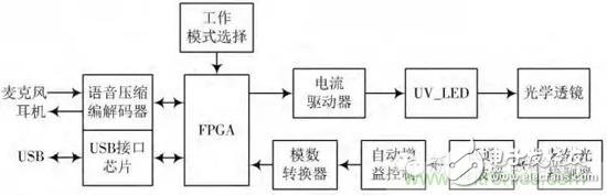
Figure 1 Block diagram of the UV communication system
Among them, the UV LED is selected from Korea's Seoul Optical Equipment Co., Ltd. T5F28, which has a wavelength of 280 nm and a transmission power of 150 mW. The photodetector uses R7154 from Hamamatsu, Japan, and its wavelength range is 160-320 nm. FPGA mainly completes four functions: timing recovery and decision of received data; data scrambling and descrambling; channel coding and decoding; data framing and de-frame.
When the system is in the transmit mode, the signal after the framing is first modulated by 2PPM, then the UV LED is driven by the current driver to generate controlled ultraviolet light; when the system is in the receiving mode, the ultraviolet ray detector receives the received light. The signal is converted into an electrical signal, which is subjected to analog/digital conversion and then sent to the FPGA for subsequent processing through a low-pass filter and an automatic gain controller.
2. Key technologies
In the design process of the ultraviolet light transmission system, the following key technologies need to be solved.
(1) Light path design
Due to the scattering propagation characteristics of the ultraviolet light, the larger the area where the field of view of the UV LED overlaps with the field of view of the detector, the more light energy is received, and the higher the received signal-to-noise ratio. Considering the UV selected by the system? The angle of view of the LED is only 10°. In order to increase the overlapping area of ​​the transmitting and receiving sides in the presence of line-of-sight occlusion, it is necessary to increase the field of view of the transmitting light source by the optical lens. The concave lens is capable of diverging the incident beam, as shown in Figure 2, so by combining a plurality of concave lenses and adjusting the UV? The distance between the LED and the concave lens provides a desired angle of view of the emission field.
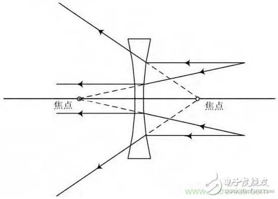
Figure 2 Schematic diagram of a typical optical path of a concave lens
(2) Timing recovery
As with conventional digital communications, the receiving end needs to clock the electrical signals output by the detector and decide on the best sampling point. On the other hand, since the modulation method takes 2 PPM, carrier recovery in a conventional digital receiver is not required here.
The clock error estimation algorithm can adopt the classic Gardner algorithm, and will not be described here.
(3) scrambling code, channel coding
In order to improve the anti-interference ability of data transmission, channel error correction coding can be added to the system. At the same time, in order to better perform timing recovery, the transmitted data needs to be scrambled. The scrambling polynomial used here is x5+x3+1, and the channel error correction coding is a (2,1,7) convolutional code whose generating polynomial is (171)o, 133o.
(4) Duplex communication protocol
In the ultraviolet communication system, since the wavelengths of the ultraviolet light source and the detector are fixed, in order to support two-way communication between multiple users, a time division multiplexing multiple access method (TDMA) and a carrier sense access method (CSMA) are adopted. ) is a better choice.
For a system with a user capacity of N, a total of N time slots are set, and each user occupies one time slot. Considering that the range of ultraviolet light communication is usually within 1 km & TImes; 1 km, the guard interval between time slots can be set very small.
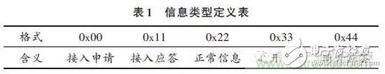
The design of the data frame structure is illustrated by taking an ultraviolet voice communication system with a capacity of 10 persons as an example. Considering that the speech rate of a person's speech is usually 160-180 Chinese characters per minute, assuming a certain margin, assuming 240 Chinese characters per minute, if the compressed speech signal rate is 4.8 Kb/s, it can be calculated. The average number of bits per kanji time is 1200b. The data frame structure designed according to this is shown in FIG. 3, wherein the information rate of the data is 60 Kb/s, the length of the information body is 1200 b, and the length of the time slot header is 96 b. The slot header includes a preamble sequence, an information type, a sender code, and a receiver code, and the lengths are 72b, 8b, 8b, and 8b, respectively. Each user only processes the time slot in which the receiving code and its own code are consistent. The transmitting and receiving parties occupy two adjacent time slots as a combination. The preamble sequence is a sequence of 0, 1 alternating, and the definition of the information type is shown in Table 1.
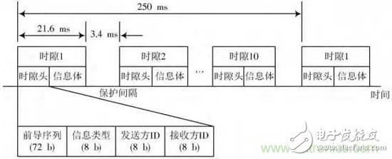
Figure 3 data frame structure design
The workflow of the entire system is as follows:
User access: If user k needs to initiate communication with user j, first listen to time slots 1~10, and if user j is busy, wait; otherwise, if there is a free time slot pair on the channel, then use the time slot pair. The previous time slot is used for access application and receives its own application information. If the received information is consistent with the transmitted information, indicating that no other user is competing for the time slot, the time slot may be occupied, and the user j sends an application response message by using the time slot of the time slot pair; if the received information and If the information sent is inconsistent, indicating that another user is competing for the time slot, the random delay Δ (the range of Δ depends on the total number of users) is the time of the data frame before the access request is made.
The user quits: If the user k or j wants to quit the system, the user needs to use the time slot occupied by the user to issue a disconnection request. After the corresponding user sends a disconnection response, both parties simultaneously release the occupied time slot pair.
System synchronization: In order to ensure the clock synchronization of the entire system and avoid overlapping of different user time slots, two measures can be taken:
(1) A guard interval of 3.4 ms is left between time slots;
(2) In addition to joining the first user of the system, subsequent users must adjust their own clocks to be consistent with the first user through phase-locked loop technology. After all users exit the system, the system's clock synchronization is restarted based on the first newly accessed user.
3. System testing
The UV transceiver module is shown in Figure 4. The board size is less than 5cm & TImes; 5cm. In order to increase the emission power of ultraviolet light, an LED array is also used at the transmitting end. The test system constructed based on the above modules shows that the transceiver parties can achieve clear voice communication of 4.8 Kb/s indoors. Subsequent testing will be conducted in an outdoor environment.
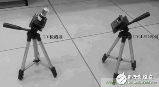
Figure 4 UV transceiver module
Conclusion
Ultraviolet light communication is not easy to detect and intercept, and can be used for non-line-of-sight communication through scattering, which is very suitable for short-distance anti-interference and communication in an occluded environment. In this paper, an LED-based UV communication system is designed. The optical path design, clock recovery, channel coding and other aspects are studied. The duplex communication protocol is designed and the link performance test is carried out. The system will be available for two-way secure transmission of voice and data.
Moulded Case Circuit Breaker is MCCB , How to select good molded case circuit breaker suppliers? Korlen electric is your first choice. All moulded Case Circuit Breakers pass the CE.CB.SEMKO.SIRIM etc. Certificates.
Moulded Case Circuit Breaker /MCCB can be used to distribute electric power and protect power equipment against overload and short-current, and can change the circuit and start motor infrequently. The application of Moulded Case Circuit Breaker /MCCB is industrial.
Korlen electric also provide Miniature Circuit Breaker /MCB. Residual Current Circuit Breaker /RCCB. RCBO. Led light and so on .
Molded Case Circuit Breaker,Small Size Molded Case Circuit Breaker,Electrical Molded Case Circuit Breaker,Automatic Molded Case Circuit Breaker
Wenzhou Korlen Electric Appliances Co., Ltd. , https://www.zjmotorstarter.com