In the oil logging industry, gamma spectroscopy measurement plays a crucial role. This paper explores the peak detection of gamma pulses by integrating pulse neutron energy spectrum analysis, employing differential circuits, delay techniques, and an FPGA device. The results demonstrate that the peak detection of gamma signals is effectively achieved, with the linearity of the process meeting the general requirements for energy spectrum measurement.
Preface
As a vital strategic resource, oil has drawn increasing attention from countries worldwide. However, it is a non-renewable energy source, and with the continuous growth of the global economy, the demand for oil keeps rising. To manage limited petroleum resources in a scientific and sustainable way, various logging methods have been developed. Among them, non-elastic, capture, and activation energy spectrum measurements have become key components in modern logging. These techniques provide valuable insights into residual oil saturation and other critical parameters. To obtain accurate spectra, a reliable peak detection and retention circuit is essential. This paper focuses on the peak detection and signal retention process in spectral data acquisition. By utilizing differential circuits, delay mechanisms, and Verilog programming, we achieve effective gamma signal peak detection, offering a practical solution for high-quality spectrum acquisition.
Gamma Signal Acquisition
Signal acquisition typically begins with a sensor. In the case of gamma signals, the sensor is known as a gamma detector. It generally consists of a scintillator, a photomultiplier tube, and a high-voltage power supply. Commonly used scintillators include cesium bromide, BGO, and sodium iodide. A detector made up of a sodium iodide crystal, a photomultiplier tube, and a high-voltage power source is used to detect gamma rays.
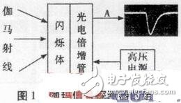
As shown in Figure 1, when a gamma ray strikes the scintillator, it produces photons. These photons are then transmitted through a photoconductive medium to the photomultiplier tube. Under the influence of the high-voltage power supply, the photoelectric signal is amplified step by step, resulting in a negative gamma electrical signal at point A. This signal is then processed by a preamplifier circuit to adjust the pulse width and amplitude, preparing it for peak detection.
Gamma Signal Conditioning
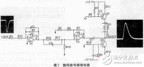
After obtaining the negative gamma signal, the next step is to modulate it to achieve the desired pulse width and amplitude, as illustrated in Figure 2. First, an inverting amplifier is used to slightly amplify the signal while reversing its polarity. An integral processing stage broadens the pulse width to approximately 1.5 μs. The amplification level depends on the energy being measured and the input range of the ADC device. In this study, the gamma ray energy ranges from 0.8 MeV to 10 MeV, and the ADC input range is 0–8 V. Thus, the entire energy range can be converted into a voltage signal between 0.64 V and 8 V, which needs precise adjustment. Calibration with a reference source is necessary but not the main focus of this paper. When the signal is amplified, it may drift from the baseline due to signal accumulation or instability in the operational amplifier. To address this, our circuit employs an active dual-diode baseline recovery method, ensuring the signal starts at the zero level and lays a solid foundation for accurate energy spectrum data.
Constant Voltage Transformer,Laminated Transformer,Encapsulated Transformer,12V Ac Transformer
IHUA INDUSTRIES CO.,LTD. , https://www.ihuagroup.com