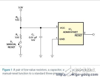
To convert a standard three-terminal reset supervisor into a manual reset system, you can simply add a pair of resistors, a capacitor, and a pushbutton switch. This modification allows for a reliable and clean reset signal whenever the button is pressed. Instead of requiring a dedicated manual-reset IC, this approach leverages the existing components to create a universal solution.
The circuit shown in Figure 1 ensures that when the manual reset button (S1) is pressed, the VCC voltage drops below the minimum reset threshold of the supervisor. This drop is caused by the voltage divider formed by R1 and R2. Once the button is released, the supply voltage returns to a level above the maximum reset threshold, allowing the supervisor to remain active until the timeout period completes.
When S1 is not pressed, the reset supervisor’s supply current and output load cause a small voltage drop across R2. For most supervisors, the supply current is around 50 μA, and if the output drives two CMOS inputs, each drawing 10 μA, the total current through R2 becomes 70 μA. This results in a 7 mV voltage drop across R2, which must be accounted for in the design.
Choosing the right values for R1, R2, and C1 is crucial. The bypass capacitor C1 should be small enough to allow the supervisor to detect any transient voltage drops. The time constant defined by R2 and C1—such as 100 Ω × 0.01 μF = 1 μs—is typically much longer than the decay rate of a regulated power supply, ensuring stable operation during power transitions.
When the manual reset button is activated, current flows through R1 and R2. In the example circuit, with a 3.3V supply, the current would be 16.5 mA. While this is acceptable for line-powered systems, it may be too high for battery-operated designs. To reduce the current, increase R1 while still ensuring the VCC voltage drops below the reset threshold. Increasing R2 also helps, but it can lead to higher voltage drops and slower transient response. Keep in mind that the increased current only occurs during manual reset, and normal system current levels are restored afterward.
By carefully selecting component values and understanding the trade-offs, you can effectively implement a manual reset function using a standard three-terminal reset supervisor. This method provides flexibility and cost savings, making it ideal for a wide range of applications.
Catering to the ever-changing demands of our patrons, we are offering them a comprehensive range of Hot Dip Galvanized Radiator. These are manufactured as per latest market trends so as to ensure their wide applications in industries. Offered products are highly demanded by the clients for their excellent design, longer service life and durability.
Galvanizing is a way of defending a steel surface from corrosion by delivering a surface coat of Zinc. The process is carried out by dipping the radiator in molten zinc bath which is upheld at a temperature of about 450 degrees.
In long-term, continuous exposure, the recommended maximum temperature for hot-dip galvanized steel is 200 °C (392 °F), according to the American Galvanizers Association. The use of galvanized steel at temperatures above this will result in peeling of the zinc at the inter metallic layer.Hdg Radiator,Oil-Immersed Hdg Radiator,Hot-Dip Galvanizing Radiator,High-Performance Hot Dip Galvanized Radiator
Shenyang Tiantong Electricity Co., Ltd. , https://www.ttradiator.com