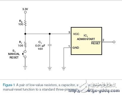
To add a manual reset function to a standard three-terminal reset supervisor, you only need to include a pair of resistors, a capacitor, and a pushbutton switch. This simple modification allows the device to be manually reset without requiring a dedicated part with a manual reset input.
The circuit shown in Figure 1 ensures a clean and stable signal when the manual reset button is pressed. When the button (S1) is activated, the VCC voltage drops below the minimum reset threshold of the supervisor due to the voltage divider formed by R1 and R2. This drop triggers the reset output. Once S1 is released, the VCC voltage returns above the maximum reset threshold, keeping the system in a valid state until the timeout period of the reset manager has completed.
When S1 is not pressed, R2 experiences a voltage drop caused by the supply current of the reset supervisor and the load on its output. Most reset supervisors have a maximum supply current of around 50 μA. If the output connects to one or two CMOS inputs, each consuming about 10 μA, the total current through R2 would be approximately 70 μA. This leads to a voltage drop across R2 of 7 mV (70 μA × 100 Ω), which adds to the reset threshold voltage.
When selecting values for R1, R2, and C1, several trade-offs must be considered. The bypass capacitor C1 should be small enough to allow the reset supervisor to detect short-term voltage fluctuations. The time constant determined by R2 and C1, such as 100Ω × 0.01 μF = 1 μs, is typically faster than the decay rate of a regulated power supply, ensuring reliable detection of voltage drops.
When S1 is triggered, current flows through both R1 and R2. In the example circuit, the current at activation is 3.3V / (100Ω + 100Ω) = 16.5 mA. While this is acceptable for line-powered systems, it may not be ideal for battery-operated devices. To reduce current, increase the value of R1 while still ensuring that the VCC voltage drops below the minimum reset threshold. Increasing R2 can also help, but it will result in a larger voltage drop and slower transient response. Keep in mind that the increased current is only active during a manual reset, and the system’s overall current draw remains low otherwise.
This approach provides a cost-effective and flexible way to implement manual reset functionality using standard components. It is particularly useful in applications where space and component count are limited, or when upgrading an existing design without major changes.
Chamfered Radiator,Galvanized Chamfered Radiator,Corrosion Resistant Chamfered Radiator,Power Transformer Chamfered Radiator
Shenyang Tiantong Electricity Co., Ltd. , https://www.ttradiator.com