1. Introduction Servo motors are widely used as actuators in automatic control systems, converting received control signals into angular displacement or angular velocity of the motor shaft. There are three common control methods: - Communication mode: Using RS232 or RS485 to communicate with a host computer for control. - Analog control mode: Controlling motor speed and direction based on the magnitude and polarity of an analog signal. - Differential signal control mode: Controlling motor speed using the frequency of a differential signal. Achieving precise and simple control of servo motor speed is a key goal in industrial automation. This paper explores how to use the analog output from a PLC to achieve more accurate speed control of a servo motor.
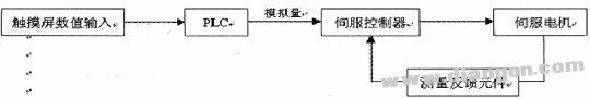
2. Control System Circuit The control system uses a Siemens S7-200 series PLC, specifically the CPU224XPCN model, which includes input/output points, as well as one analog input and one analog output point. The touch screen used is the Siemens TP177B model. The overall control scheme is illustrated in Figure 1. The touch screen serves as the human-machine interface, where initial commands are entered. These commands are sent to the PLC via a communication port. The PLC then outputs an analog signal to the servo controller's analog input. The controller processes this signal internally and drives the motor to the desired speed. A speed measuring component provides feedback to the controller, forming a closed-loop system that ensures stable operation.
Figure 1: Control Scheme
The servo motor in this setup operates within a design speed range of 500 to 6000 RPM, with an accuracy requirement of ±3 RPM.
3. Control Process A dialog box is set up on the touch screen, allowing users to input a four-digit value. This value is mapped to a corresponding variable in the PLC, such as VW310. The objective is to ensure that the motor reaches the same speed as the input value. The PLC’s analog output ranges from 0 to 10V, corresponding to shaping data values of 0 to 32000. The servo motor’s analog input also accepts 0 to 10V, corresponding to a speed range of 0 to 6500 RPM. However, due to theoretical limitations, the actual speed must be calibrated. Direct measurements showed discrepancies between input values and actual speeds, as shown in Table 1.
Table 1: Direct Measured Value Table
| Input value | Shaping value | Actual speed |
| 500 | 500 | 70 |
| 2000 | 2000 | 360 |
| 4000 | 4000 | 750 |
| 6000 | 6000 | 1145 |
From Table 1, it’s clear that the input value doesn’t directly match the actual speed. Therefore, a conversion process is needed to map the input value to the correct shaping value. By experimenting, we determined the relationship between the shaping value and the actual speed, as shown in Table 2.
Table 2: Measured Corresponding Value Table
| Shaping value | Actual speed |
| 2711 | 500 |
| 30854 | 6000 |
Both the PLC’s analog output and the servo motor’s speed output follow a linear relationship. Using these values, we derived the following equation:
y = 5117 × x + 152
Where y is the shaping value and x is the actual speed. To implement this in the PLC, a digital operation instruction was used. The calculated value is then transmitted to the analog output port, as shown in Figure 3. This allows the PLC to send the correct signal to the servo controller, ensuring the motor runs at the intended speed. After testing, the results are shown in Table 3.
Table 3: Measured Value Table After Operation
| Input value | Shaping value after calculation | Actual speed |
| 500 | 2711 | 500 |
| 1000 | 5269 | 999 |
| 2000 | 10386 | 1998 |
| 3000 | 15503 | 3000 |
| 4000 | 20620 | 4002 |
| 5000 | 25737 | 5001 |
| 6000 | 30854 | 6000 |
4. Conclusion This paper presents a practical method for controlling a servo motor using the analog output module of a Siemens S7-200 PLC. The approach is straightforward, easy to implement, and meets the required precision of ±3 RPM for rotational speed. It demonstrates the effectiveness of combining PLCs with servo controllers for precise motion control in industrial applications.
We have supplied our Lighting poles to Australia, Columbia, England, Kuwait, Iraq, Philippines, Pakistan and etc.
Our Lighting poles are made from quality sheet through bending, forming, automatic welding and hot galvanization. We can reach one-run machining length of 14m and can bend sheet of thickness up to 45mm. We adopt advanced welding procedures, automatically weld main joints and reach rank-II welding quality.
Lighting Pole, Transmission Line Pole, Solar Lighting Pole, Single Arm Lighting Pole
JIANGSU XINJINLEI STEEL INDUSTRY CO.,LTD , https://www.steel-pole.com