First, the cause of leakage problems
Some on-site use inverter to control the motor, there will be leakage problems, and the leakage voltage may vary from tens of volts to two hundred volts. In response to this problem, the theoretical analysis and explanation of the causes of this fault are presented below.
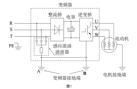
According to the functional block diagram of the inverter control motor operation (Fig. 1), the three-phase power supply is rectified by the inverter rectifier bridge, and then sent to the inverter bridge (IGBT) through the capacitor filter, and then the inverter bridge output frequency and voltage adjustable three. Phase alternating current to control the operation of the motor. Three alternating currents of 120 degrees out of each other flow through the three-phase stator coil windings of the electric motor to generate a rotating magnetic field, so that the rotor of the electric motor automatically rotates under the action of the rotating magnetic field of the stator winding.
We all know that a rotating magnetic field is generated after the three-phase stator winding of the motor flows, and according to the principle of electromagnetic induction, the outer casing of the motor generates an induced electromotive force. The magnitude of this induced electromotive force depends on the switching frequency of the inverter IGBT and C*DV/DT (related to the switching speed of the IGBT); since the high-performance control requires a higher switching frequency, the switching speed requirement is higher. Fast, then DV/DT is too large. If this induced electromotive force is large, then people will feel the shock when they touch it. In theory, the higher the switching frequency of the IGBT, the higher the effective value of the induced electromotive force of the motor casing (ie, the induced voltage), and the higher the control precision and dynamic response of the inverter to the motor, the feeling of being electrically felt after the human body touches. On the contrary, the lower the switching frequency of the IGBT, the lower the effective value (induced voltage) of the induced dynamic potential of the motor casing, and the smaller the feeling of being charged after the body touches. Therefore, the switching frequency of some domestic low-end inverter IGBTs is designed to be low. After the motor is controlled, the induced voltage of the motor casing is lower, but its control performance is poor and the dynamic response is slow. The performance and dynamic response of our inverter are good, so the switching frequency and switching speed of our inverter IGBT are higher, and the induced electromotive force is relatively larger.
Since the asynchronous motor operates, the motor casing will have an induced voltage (so-called leakage). Therefore, the motor manufacturer will install a grounding terminal in the junction box when the motor is shipped, so that the user can connect to the ground during application to eliminate It induces an electromotive force (ie, eliminates the induced leakage voltage) to solve the feeling of being charged when the human body contacts the motor. Of course, when the motor is running at the power frequency, the switching frequency of the power frequency is about 50 Hz, which is very low, so there is almost no leakage feeling under normal conditions (unless the motor insulation is poor). When the inverter is controlled, since its switching frequency is much higher than the power frequency, the inverter will have a leakage feeling when controlling the motor to rotate.
Second, the solution to the leakage problem
In order to avoid this problem, the inverter hardware is designed with an inductive surge filter circuit (the equivalent circuit is shown in Figure 1), and the grounding terminal of the inductive surge filter and the inverter The outer casing is connected. At the same time, in the wiring description of the inverter, it is required to connect the ground terminal of the motor to the ground terminal B of the inverter, and connect the ground of the input power (ie, the ground) to the ground terminal A of the inverter.
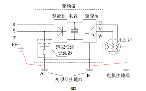
Therefore, the induced current generated by the motor operation can be looped through the ground line of the motor and the inverter, and the ground line between the inverter and the power source, so that the ground of the motor, the ground of the inverter, and the ground of the power source (ie, the ground) are equal. At the potential, the potential difference between them is 0 volts. In this way, the human body stands on the ground (also the ground of the power supply) and contacts the rotating electric casing and the frame of the mechanical equipment (the frame of the general equipment is connected to the earth), and the outer casing of the inverter will not The feeling of being electrically, because the potential difference (voltage difference) between them is 0 volts, the human body can not feel whether there is electricity.
When the ground wire of the motor fails to connect with the grounding end of the inverter, and the ground wire of the power supply is not connected with the ground of the inverter, the outer casing of the mechanical equipment or the grounding end of the electric motor, the outer casing of the motor and the frequency conversion The outer casing of the device and the ground of the power supply (ie, the ground) are not at the same potential. If in this case, the induced voltage generated by the motor operation is 100V, the motor is racked together with a certain part of the mechanical equipment, because the ground wire of the power supply is not pulled in the power distribution room, and the human body's electrical equivalent model theory It can be equated with a resistance of about 2K ohms (if the human body sweats, the resistance value is smaller when wet, sometimes even only a few tens of ohms), when the human body stands on the ground and touches the metal of the equipment connected to the motor, the induction current of the motor (such as 100V) can discharge the earth to the earth, then the human body will have a current flowing, there will be a feeling of being charged. Although, in theory, the motor casing is connected to the frame of the mechanical equipment, and the frame of the equipment is mounted on the ground, it is reasonable to say that the person standing on the ground and touching the equipment frame should not be electrically shocked by induction. However, don't forget that although the earth is also a conductor, the earth is resistant, after all, and the resistance varies according to the soil composition of different land. Otherwise, why does the National Power Supply Bureau require that the grounding resistance of each substation transformer and the grounding resistance of each company's power distribution room be less than 4 ohms? Why is it not allowed to be approved if the grounding resistance of the substation or high-voltage power distribution room is not less than 4 ohms? In fact, this is the truth. When there is a distance between a person and a device, there will be an induced voltage. When the human body touches the device, there will be a current flowing through the human body, and there will be a feeling of being electrically charged. It is only the size of the induced electricity, and the size of the person being determined by the electricity is different.
However, in some factories, for the convenience of wiring, the ground wire inside the high-voltage power distribution room is not pulled into the production workshop, and even the wrong ground is that the earth is the ground wire. Why do you want to pull the ground wire? Isn't it more than one thing? This kind of thinking is wrong. Everyone can't think about it. If the earth can be used as a ground wire, why should all the wires in our daily life pull N lines and ground lines? The N line inside the power station is actually connected to the ground line? Can we save a lot of cables and wires without pulling the ground wire and the N wire? Why do you have to do this work that wastes manpower, wastes material resources, wastes time, and wastes money?
However, in reality, some factories do not pull the power ground, the equipment can not find the grounding point, and the motor is in use in the case of induced leakage, how to deal with this situation? Here, we propose two options as follows:
Solution 1: Connect the grounding end of the motor casing and the frame of the mechanical equipment to the grounding end of the inverter (Figure 3).
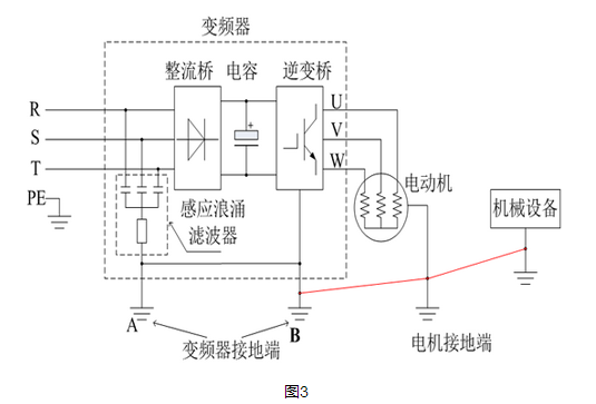
After the ground wires of the motor, the inverter and the frame are connected together, they are at the same potential, and are absorbed and discharged through the induction surge filter circuit inside the inverter, so that the induced voltage is greatly reduced, thereby The induced electric power generated by the rotation of the motor is also greatly reduced with respect to the ground of the power source (i.e., the earth), so that there is no feeling of being electrically charged after being touched by a person. That is to say, it does not matter if there is no power ground, as long as the ground of the motor, the ground of the inverter and the frame are connected together, so that the inductive electric surge filter inside the inverter will play a real role.
Option 2: Under normal circumstances, after the treatment of the first scheme, the induced voltage generated by the rotation of the motor is already very small, and it will not leak electricity, but for some special reasons (such as: poor motor insulation, electrical cabinet When there is no grounding, etc. when the appliance is installed, the induced voltage is still high, and there is a feeling of leakage of electricity, and the second scheme is proposed.
In the second scheme, an inductive surge filter is added to the input power terminal of the inverter under the premise of the first scheme.
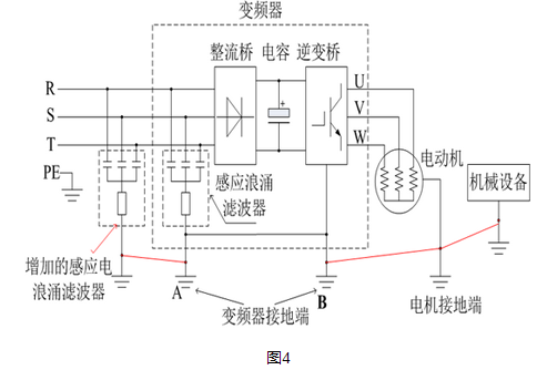
Connect the ground of the inductive surge filter to the ground of the motor and the ground of the inverter (as shown by the red line in Figure 4), so that the inductive surge filter absorbs the induced current of the motor again. And venting, further reducing the induced voltage to achieve the current prevention of leakage. The circuit principle of the increased inductive surge filter is the same as the surge filter circuit inside the inverter. It is too large to be designed and installed in the internal circuit of the inverter, so it is made externally.
We have had a lot of experiments to prove that the on-site rectification of the connection method of the second scheme can reduce the induced voltage generated by the motor operation to below 20V in the application of the ground wire without the power supply, ensuring the on-site operator. The safety will no longer be felt by people who are leaking electricity. However, if the ground wire of the power cord is connected in the second scheme, then no external inductive surge filter is needed.
In addition, if there are multiple inverters in the field to control the motor operation, and it is not convenient to install multiple inductive surge filters, it is not necessary to require each inverter to be equipped with an inductive surge filter. Connect only one or two inductive electric surge filters, and connect the grounding end of the filter to the grounding end of several inverters in the field, the grounding end of the field motor, and the equipment rack, as shown in Figure 5:
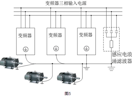
Since each inverter has an inductive surge filter circuit inside, if the ground wire of the motor is not connected to the ground terminal of the inverter, the inductive surge filter will not work, so the field application The ground terminal of the medium motor must be connected to the ground terminal of the inverter. Of course, some equipments do not have ground leakage when the motor is not grounded. In some cases, the earth is also a conductor, but the earth is resistant, and according to the soil composition of different land. The resistance is also different in size. The principle is the same. However, according to the correct electrical safety regulations, the motor is required to be well grounded, but the conditions are not allowed (if there is no power supply ground), the ground of the motor, the cabinet of the electric cabinet and the ground of the inverter can always be connected together.
For the 66kV Oil Immersed Power Transformer, we can produce capacity upto 180MVA. We use the best quality of raw material and advance design software to provide low noise, low losses, low partial discharge and high short-circuit impedance for power transformer.
Our power transformer are widely used in national grid, city grid, rural grid, power plant, industrial and mining enterprise, and petrochemical industry.
Rectifier Transformer,66Kv Power Transformer,66Kv Transformer,66Kv Transformer With Octc
Hangzhou Qiantang River Electric Group Co., Ltd.(QRE) , https://www.qretransformer.com