The original wireless local area network (WLAN) standard was primarily used to provide wireless broadband connections with low data rates for wired broadband connections to browse web pages and email. Over time, the new 802.11 wireless protocol provides a higher data transfer rate for new applications. Table 1 shows the progress of the 802.11 WLAN standard.
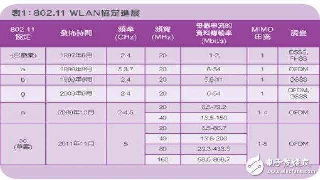
Table 1: Progress of the 802.11 WLAN Agreement
The latest 802.11ac WLAN standard, still in draft form, will deliver data rates of up to 867 Mbps in a single radio frequency (RF) channel and 6.93 Gbps when using multiple input multiple output (MIMO) channels. Extend the 802.11n standard to a higher 802.11 by using more immediate bandwidth (up to 160MHz), more MIMO channels (up to 8), and high-density modulated constellations (up to 256QAM) Ac data transfer rate. This article explores the need for new validation of 802.11ac requirements for power amplifier design verification, features, and testing.
Power amplifier test
Power amplifiers (PAs) are key components in WLAN transmitter circuits because PA performance can affect wireless coverage, data rate capacity, and battery life. The goal of any transmitter PA is to use as little DC power as possible to generate sufficient linear RF output power. When the output power is increased to the gain compression region of the amplifier, the PA performance can dominate the WLAN system level transmitter performance due to PA nonlinear distortion. Mobile devices and wireless access points typically transmit RF output power between 100 mW (+20 dBm) and 1 W (+30 dBm), and the PA must be capable of producing sufficient power with minimal nonlinear distortion.
For PA testing, a complete IEEE 802.11ac specific transmitter compatibility test is available for spectrum masking, spectral flatness, peak power, center frequency error, symbol clock frequency error, center frequency leakage, and error vector size ( EVM) and other tests. This article will explore EVM testing further – a comprehensive and widely used technique for PA testing. The EVM is a measurement used to quantify the performance of a digital communication channel and provides a deviation measurement from the coded data symbols it has captured from the ideal position within the I/Q constellation. The rms EVM is a comprehensive measurement that reduces any defects in the RF signal or device. Therefore, for WLAN transmitter designs, the PA requires an acceptable EVM action over the full operating range of its output power and channel frequency.
Since 802.11ac includes a 256QAM cluster with a 2.5% (-32dB) EVM specification limit, PA linearity and corresponding EVM action requirements are more stringent than earlier 802.11 standards, while PA's EVM for 802.11n is limited to approximately 3%. The PA's EVM action limit for 802.11ac is about 1.5%. In addition, the new 256QAM signal modulation has a higher peak-to-average ratio (PAR) and also increases the linear output power necessary for PAs in 802.11ac transmitter designs.
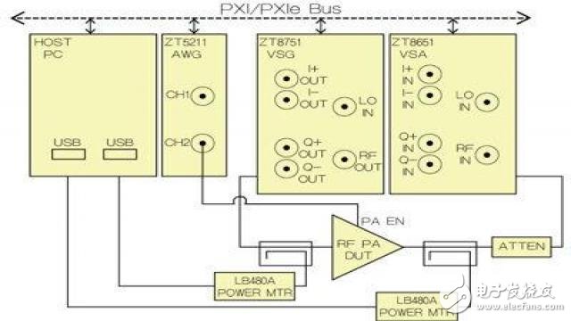
Figure 1: Test equipment architecture diagram for PA testing
Figure 1 shows a general test equipment architecture diagram for PA testing using the ZEC instrument z8201 RF test suite. The general equipment list includes the z8651 6GHz Vector Signal Analyzer (VSA) (optional 80 or 160MHz analysis bandwidth), z8751 6GHz Vector Signal Generator (VSG) (optional 250 or 500MHz), variable width, z5211 200MS/s Waveform generators, see the Ladybug Technologies LB480A USB power meter, PXI/PXIe chassis and host computer, as well as cables, directional couplers and attenuators.
Since the PA input and output power are set and measured by VSG and VSA, a USB power meter and associated directional coupler can be selected as needed. The power meter provides a more accurate PA input and output power correction measurement with a directional coupler at the DUT. The VSA and VSG are usually accurate to "0.5dB, while the power meter can be accurate to "0.1 dB. The correction factor for the attenuator and for the directional coupler when using the power meter configuration must be pre-corrected.
PA EVM
The EVM test for PA generally measures the output power of the EVM relative to the PA by a number of test frequencies. Figure 2 shows the actual measured data curve for a general PA EVM test using the z8201 RF test suite. These curves show that all five 80MHz 802.11ac channel frequencies tested are suitable for PA over a 30dB input power range. The actual PA output power is measured using a power meter and provides information to the horizontal axis of the graph of Figure 2.
In this test, there were 5 channel frequencies and 30 powers in all 150 test points. One of the advantages of the PXI/PXIe highly integrated test equipment architecture is the fast data throughput and processing speed. In 150 test cases, the total test time can be significantly reduced compared to other test equipment such as LAN or GPIB interfaces. For the z8201 RF test suite and zProtocol WLAN software, sample code is provided to optimize the setup and operation of the 802.11ac test to achieve a fast 20ms per EVM measurement.
When discussing the actual PA test data shown in Figure 2, it can be found that the EVM is reduced at high output power. As the PA output power increases to its gain compression region, nonlinear distortion occurs and the EVM increases. This EVM power sweep test identifies the linear power region of the PA, which is a key factor in the design considerations of the WLAN transmitter. In addition, in order to achieve a critical value of 802.11ac below 1.5% EVM, this particular PA can achieve a maximum output power of +10dBm; although this PA is designed for 802.11n transmitters and works well, there is no such as digital pre- For 802.11ac transmitter designs with additional linearization techniques such as distortion, the linear output power is insufficient.
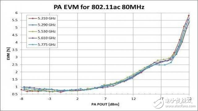
Figure 2: Comparison of PA EVM and output power
Dynamic EVM
Battery life and power consumption are important considerations for system-level WLAN transmitter designs. Since PA emissions consume a significant portion of the total system DC power, some techniques must be used to reduce PA power usage. Many PAs provide an adjustable DC supply voltage that optimizes the maximum RF output power relative to DC power consumption, and most PAs can be powered down or deactivated when not in use to conserve power, such as receiving or intervening during transmission. between. To maximize power efficiency, the PA must have fast turn-on and turn-off switching times. Figure 3 shows the PA enable (PA EN) and RF pulse signals relative to the pulse taken by the oscilloscope with a 50% duty cycle. Please note that the adjustable delay between the PA EN pulse and the RF signal is set to 2.0us in this test setup. The highest DC power benefit occurs when the time difference between the PA EN and the RF signal is minimal, but a short delay can exacerbate the transient effect on the RF signal.
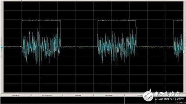
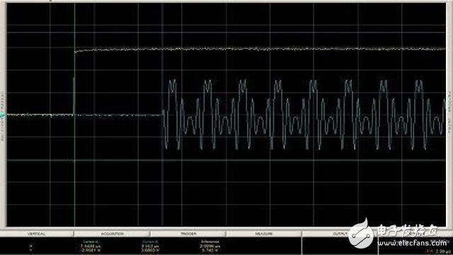
Figure 3: Time domain plot of PA enable (yellow) and RF pulse (blue)
Since the power/de-energization of the PA may cause transient and thermal effects that degrade transmitter performance, another metric called dynamic EVM is typically tested. The dynamic EVM is measured with the actual dynamic operating square wave applied to the PA EN analog transmitter. The reduction of dynamic EVM is caused by the influence of the preamble signal at the beginning of the packet and the PA transient response of the defect channel estimation. Studies have shown that dynamic EVM with a 50% duty cycle square wave is less suitable for PA EN than static EVM (PA EN with 100% duty cycle).
Using the test equipment shown in Figure 1, dynamic EVM testing is fully automated with PXI/PXIe systems. Use PXI/PXIe backplane triggers and clock signals to achieve full time synchronization of dynamic EVM measurements. The block diagram of Figure 1 shows the z5211 Arbitrary Waveform Generator (AWG), which produces PA EN pulses with adjustable voltage magnitude, pulse width, pulse delay, and repetition rate.
The actual PA test data in Figure 4 shows that the dynamic EVM is not worse than the static EVM until the +18dBm output power. For this particular PA, the dynamic EVM is better than the static EVM above +18 dBm output power. As noted earlier, this type of PA dynamic EVM measurement is critical to transmitter design considerations due to the performance of the dynamic EVM when the PA is used in the actual pulse mode of operation.
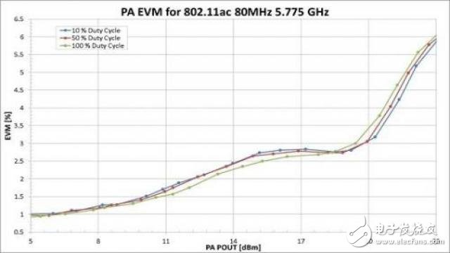
Figure 4: Comparison of PA dynamic EVM and duty cycle
Digital predistortion
Improving PA linearity with high output power is a challenge. Digital Predistortion (DPD) is a technique used to remove distortion substantially by digital signal processing techniques. Software tools simplify and automate DPD for combined VSA/VSG test systems such as the z8201 RF test suite. Basically, the software model is used to measure the nonlinearity of the PA with the VSA and form a reverse operation for the VSG; when the DPD compensation is completed, the predistorted VSG RF signal is applied to the PA that effectively linearizes the PA output.
Some 802.11ac WLAN transceiver chipsets use DPD technology to improve PA linearity. In order to quantify the degree of improvement achievable in a circuit with DPD, the test equipment must be able to perform DPD during PA characterization. In addition to the z8201 RF test suite and zProtocol WLAN software, ZEC Instruments' DPD software tools and corresponding sample code provide a quick and easy way to evaluate the PA or transmitter design DPD. Because DPD algorithms require VSG/VSA instruments to capture multiple adjacent channels, DPD applications require wide measurement bandwidth such as the z8201 RF test suite.
Figure 5 shows the improvement of DPD in adjacent channel leakage (ACL) from nonlinear distortion when the PA is operating in its non-linear region; equally important is the EVM improvement that can be achieved by DPD as shown in Figure 6. Both figures depict the actual data obtained using the zProtocol WLAN and DPD software with the z8201 RF test suite.
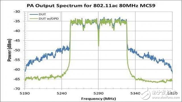
Figure 5: Reducing PA adjacent channel leakage with DPD
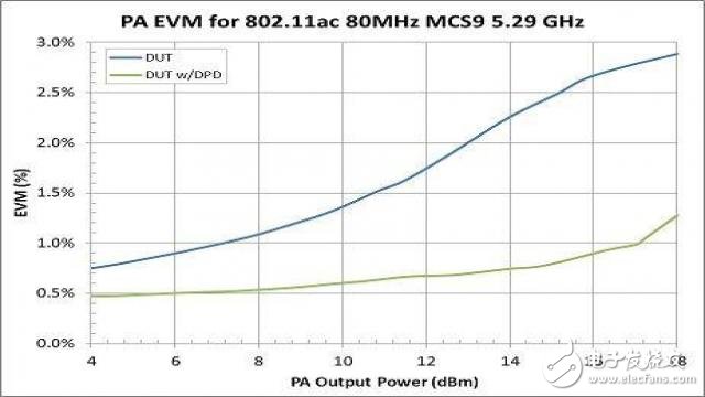
Figure 6: Improving PA EVM with DPD
Test Equipment
For 802.11ac testing, the noise level, phase noise, intermodulation distortion, and intra-frequency spur signals of the test equipment must be minimized to avoid degrading the measured PA EVM performance. Figure 7 shows the residual EVM effect of the test equipment on the measured PA DUT EVM.
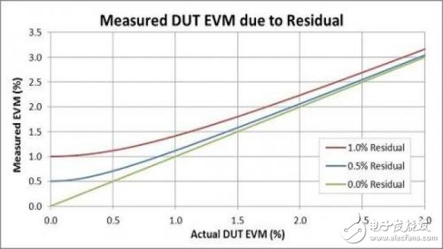
Figure 7: Residual EVM effect of test equipment on the measured DUT EVM
Figure 8 shows that the z8201 RF test suite consists of a 6GHz VSG/VSA integration with a measurement bandwidth of up to 160MHz. In addition to the wide measurement bandwidth, the z8201 RF test suite provides the low noise and distortion necessary for 802.11ac device characterization and testing. The z8201 RF test suite provides up to 0.3% exception back-remaining EVM bottom for 20MHz 802.11ac and 0.7% for 160MHz 802.11ac (phase tracking, pre-signal guidance data equalization); in addition, add z8801 LO module The z8221 RF test suite achieved a residual EVM bottom as low as 0.2% for 20MHz 802.11ac and 0.4% for 160 MHz 802.11ac.
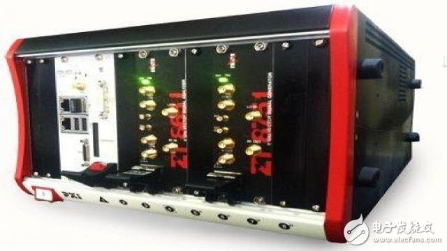
Figure 8: z8201 PXI or PXIe RF Test Suite
The zProtocol WLAN software toolset includes the intuitive graphical user interface (GUI) shown in Figure 9, as well as a comprehensive C/C++/LabVIEW software driver for easy automation. The z8201 RF Test Suite, combined with zProtocol WLAN software, provides a complete solution for 802.11 testing covering all aspects of the WLAN protocol, including:
All adjustable conversion width: 160MHz, 80MHz, 40MHz and 20MHz
All modulation coding schemes (MCS) and bit rate: BPSK to 256QAM
All channel frequencies: 2.4 GHz and 5 GHz bands
MIMO stream: X2 to X8
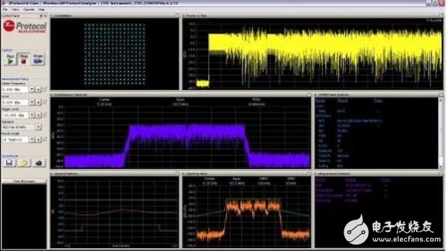
Figure 9: zProtocol WLAN Test Software GUI
The sample automation code provides valuable reference demonstration automation use cases and allows the user to begin characterization or design verification with a little additional programming or integration. All of the specific PA tests described in this article are available and can be downloaded from the ZTEC Instruments website as a sample code.
Conclusion
This article explores the design verification, characterization, and testing requirements of the new 802.11ac WLAN standard for power amplifiers (PAs). With a PA EVM effect on 802.11ac limited to approximately 1.5%, PA and RF test equipment require higher linearity and dynamic range requirements. This article defines a number of techniques for 802.11ac PA testing that help test device optimization. These technologies are used in conjunction with the z8201 RF test suite and zProtocol WLAN software to provide a complete solution for quantifying PA performance for 802.11ac WLAN transmitter design operations. Program.
Glass Door Chiller,Glass Door Freezer,Glass Door Display Freezer,Glass Door Refrigerator Freezer
ZHENGZHOU KAIXUE COLD CHAIN CO., LTD. , https://www.supersnowfreezer.com