Have you encountered fluctuations in capacitance measurements in the sensor system? There are several explanations for fluctuations in these measurements, but the most common root cause is external parasitic capacitance interference. Such interference, such as inadvertently leaning too close to the hand or electromagnetic interference (EMI) in the surrounding area, needs to be brought to our attention and solved in the system design because the interference will greatly reduce the system. Reliability and sensitivity. Fortunately, there are several ways to help alleviate these disturbances so they don't affect the capacitance measurements; one of them is active shielding. The biggest feature of the FDC1004 is that it has a sensing area that reduces interference and helps concentrate the capacitive sensor.
Imagine having a wire connected to one of the FDC1004 channel inputs. When your hand is near this wire and will be in contact with it, the signal on the hand and the wire forms a closed loop, at which point the human body acts as a ground source. If your hand is not the intended target, then it is considered a parasitic capacitance. The solution is to set up an active shield wrapped around the wire. The shield driver is an active signal output that is driven as a sensor input at the same voltage potential, ie, the same waveform, so there is no potential difference, so there is no capacitance between the shield and the sensor input. Any external interference will couple the shielded signal with minimal interaction to the sensor signal. Figure 1 shows how the shielding of the sensor to the signal line of the FDC1004 reduces the effect of any source of interference on the capacitance measurement.
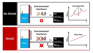
Figure 1: Comparison of shielded and unshielded
There are several advantages to using shielding in capacitive sensing applications :
1. It points and focuses the sensing area in a specific area.
2. It reduces and eliminates parasitic capacitance and sources of interference.
3. It eliminates the effect of temperature changes on the ground plane.
Shielding directivity
When there is no shielding, the sensor, CH, detects the objects above and below the sensor. Depending on the application, it is not appropriate to simultaneously detect objects above and below, and incorrectly represent capacitance measurements associated with the target. By placing a shield sensor beneath the CH and GND electrodes, the lower field line is essentially blocked; only the top field line has a defined path. The example shown in Figure 2 is somewhat simplified and does not include edge effects.
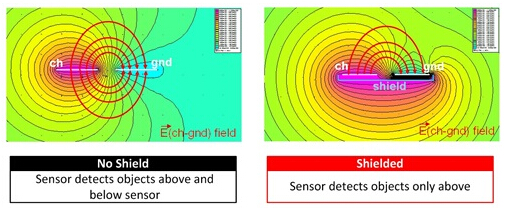
Figure 2: Electric field lines between CH and GND
Parasitic capacitance and interference source
Good system-level design principles require ground planes to help reduce noise and increase signal integrity. For capacitive sensing applications, the ground plane can have a negative impact because the ground plane produces a termination source for the electric field lines even if it is not a defined sensing area. If the printed circuit board (PCB) is stacked in a similar manner as in Figure 3, edge effects will occur and will result in values ​​within the measurement path from the sensor to the ground plane. This high value ground parasitic capacitance can be significantly reduced by using a shield between the sensor and the ground plane.
Ideally, this shield will eliminate the full effect of the ground plane; however, due to edge effects, there will still be a small parasitic ground capacitance value in the measured value. The shield size must be much larger than the size of the sensor and ground plane so that the field lines on the edges are much weaker than the overall capacitance measurements.
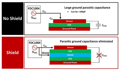
Figure 3: Ground plane effect with and without shielding
Temperature effect on the ground plane
In addition to introducing an initial parasitic capacitance shift into the measured value, temperature is also a factor that causes the parasitic ground plane capacitance to change. This phenomenon can be seen as an offset that changes over time. The changes caused by these temperatures are caused by the expansion and contraction of the ground plane. Inserting a shield between the sensor and the ground plane helps to mitigate the effects of parasitic ground plane capacitance on the measured value.
Typical implementation when using FDC1004
The FDC1004 has the ability to drive a 400pF load on the shield driver pins. Any load greater than 400pF will prevent the shield from functioning properly. The pairing between the input channel and the shield depends on the mode of operation. In single-ended mode, CIN1 to CIN4 can be paired with SHLD1 or SHLD2 because the two shield pins are internally shorted together. For differential mode, Table 1 lists the conditions within the phase.
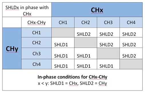
Table 1: Channel and Mask Pairing for Differential Mode
For example, if FDC 1004 is configured as CH1-CH4, CH1 will be in phase and paired with SHLD1, while CH4 will be in phase and paired with SHLD2.
Author: David Wang, Texas Instruments
LED emergency power supply is a driver that can be used as backup power supply for LED lights . The Aluminum Shell Emergency Driver can be applied to all different types of LED lights in the wide range of AC85-265V . Aluminium housing can make the Emergency Conversion Kit faster heat dissipation , small density and light weight , with a strong corrosion resistance . Choose high quality rechargeable lithium ion battery to extend the service life .

Aluminum Shell Emergency Driver
Emergency Light Kit,Led Emergency Inverter,Led Emergency Backup Driver,Led Light With Emergency Backup
Jiangmen City Pengjiang District Qihui Lighting Electrical Appliances Co., Ltd , https://www.qihuilights.com