Electrocardiogram (ECG) is a science that converts the ionic depolarizaTIon into an measurable electrical signal for analysis. One of the most common challenges in analog electronic interface to electrode/patient design is the optimization of right leg drive (RLD) for high common mode performance and stability. This design process can be greatly simplified with SPICE analysis.
In the ECG front end, the RLD amplifier has a common-mode electrode bias of Vref and feeds back the inverted common-mode noise signal (enoise_cm) to reduce the total noise at the input of the gain stage of the measurement amplifier. In Figure 1, the source ECGp and ECGn are separated to show how the RLD amplifier provides a common-mode reference point for a portion of the ECG signal that can be seen at the positive and negative inputs of the measurement amplifier (INA). The parallel RC combination of the left, right, and right legs represents the lumped passive electrode connection impedance (represented by 52k? and 47nf later in this article). Assuming that enoise is parasitically coupled to the input, the feedback of enoise_cm reduces the total noise signal at each input and filters the residual noise using an external method, or suppresses it by using the common-mode rejection ratio (CMRR) of the measurement amplifier.

Figure 1 LEAD I and RLD Easy Connection
In Figures 2, 3, and 4, we can see the common mode rejection variation, indicating that the common mode test circuit has different RLD amplifier gains. These figures show that the best low-frequency CMRR is achieved without a feedback resistor (ie, the gain is infinite); however, in the real world, for applications that require the RLD amplifier to run linearly after an input amplifier lead is removed It may not be practical to remove the DC path and/or set the RF to a high value.

Figure 2 Relationship between CMRR and RLD gain
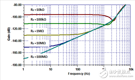
Figure 3 CMRR diagram vs. frequency and RLD gain (RF)
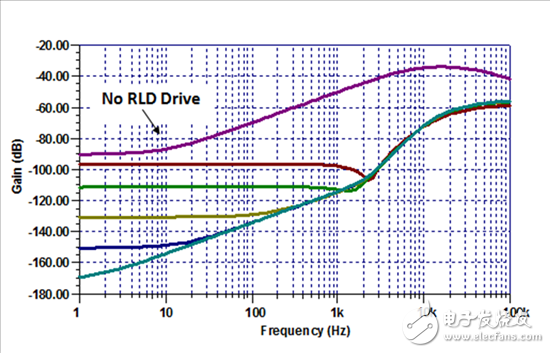
Figure 4 Relationship between MCRR RLD and no RLD
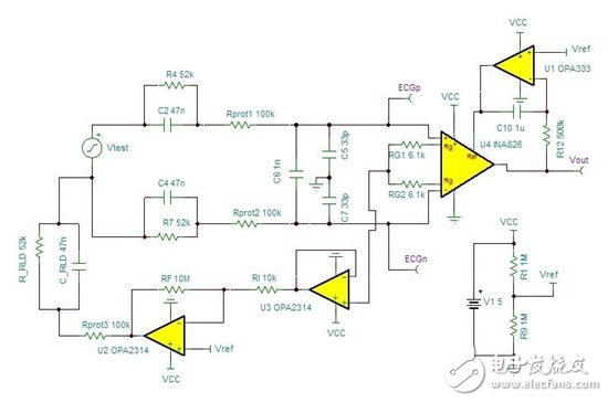
Figure 5 small signal pulse test circuit

Figure 6 Figure 5 output curve
Once the gain of the RLD amplifier is determined, the test circuit shown in Figure 5 can be used and a small signal step is injected into the loop and the output response is monitored. At this point, the response (shown in Figure 6) shows a strong output oscillation indicating instability in the loop. The main feedback path that causes this instability is the body/electrode/measurement amplifier feedback path around the RLD amplifier. The test circuit shown in Figure 7 allows the feedback and open-loop gain (AOL) plots of the RLD amplifier to be analyzed separately on a Bode plot.
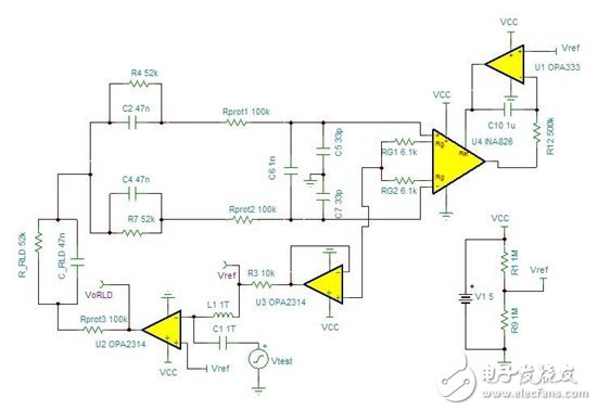
Figure 7 Electrode / Measurement Amplifier Feedback Test Circuit
The 1/β (feedback) graph shown in Figure 9 represents the simulation results of Figure 7. Note that in the absence of an external compensation network, the 1/β curve is close to the AOL curve and the approach rate (ROC) is 20 dB/dec, which indicates the presence of instability (proven process, not discussed here). To solve this problem, add a series Rc and Cc (Zc shown in Figure 9) to the local feedback of the RLD amplifier, so that the total 1/β crosses the AOL curve with a proximity rate (ROC) ≤ 20dB/dec, and The loop gain complement angle is 45° (Fig. 12). After that, Zc becomes the main feedback path between 20k-30kHz. Figure 11 shows this new, compensated 1/β plot (based on Rc and Cc differences).
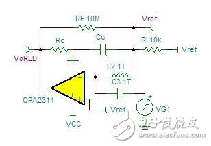
Figure 8 compensation network test circuit
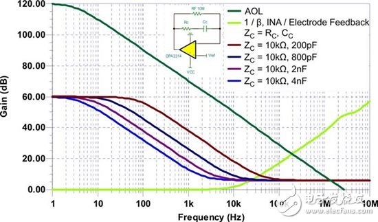
Figure 9 AOL, 1/β, and Zc
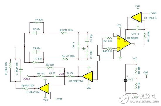
Figure 10 compensated right leg drive

Figure 11 AOL and 1/β for different Cc values
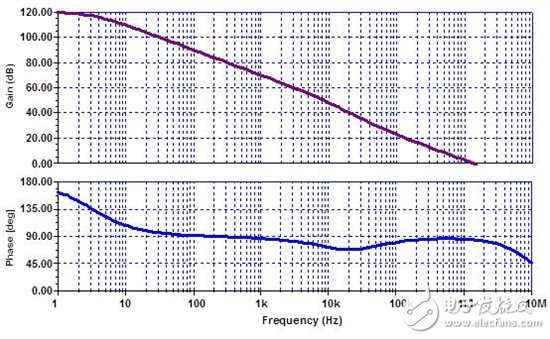
Figure 12 Figure 10 Loop gain and phase
In summary, SPICE is an effective tool to quickly analyze and optimize the performance and stability of RLD front-end circuits. Keep in mind that the quality of the model determines the quality of the simulation, so it is important to model some important specifications, such as noise, AOL, open-loop Zout, and CMRR versus frequency. In addition, this work should be completed before the analysis and design begins.
Author: Matthew Hann, Texas Instruments
See the original text: http://
The Texas Instruments online technical support community provides technical support for Chinese electronics engineers to answer technical challenges. The German instrument community involves analog electronic technology, microcontroller, MCU, embedded system, DSP, digital signal processing, and is the preferred technology exchange platform for electronic engineers using TI chip design. For more forums, please visit: http://
In order to meet customer commercial use, we developed and strongly recommend our 5.5inch PDA Handheld Terminal. With its stylish and fashionable appearance, it gains popularity in market. It is not only a Barcode Scanner PDA with built in printer, but also can support expand functions such as UHF reader, Fingerprint scanner, IC card reader and etc. Welcome to contact us for more information!

5.5inch PDA Handheld Terminal
Pda Rfid Scanner,Pda With Fingerprint Scanner,Pda With Built In Scanner,Android Handheld Terminal With Printer
Shenzhen Qunsuo Technology Co., Ltd , https://www.qsprinter.com