With the development of market demand and technology, people have put forward higher requirements for the reliability and stability of engineering, machinery, aviation and marine equipment. Attitude measurement is an important indicator. The tilt sensor is a device that measures the tilt angle or attitude with respect to a certain reference plane. Currently, there are single-axis, two-axis, and three-axis tilt sensors on the market, but most of them are expensive or bulky. This paper proposes the design of the dual-axis sensor SCA100t and C8051F single-chip microcomputer, which can greatly reduce the system cost. It can not only form a single digital output sensor, but also can be used as a measurement module embedded in the measurement control system. It is widely used in robot control. Platform attitude (pitch and roll) measurements, biaxial acceleration measurements, etc.
Hardware circuit design
The overall system structure is shown in Figure 1. Can be divided into power supply circuit, angle measurement and data acquisition and output. The system is powered by a wide power supply. After power conversion, the power supply is divided into two paths. One is controlled by a precision voltage regulator chip REF195, which outputs a highly stable 5V voltage, which is specially designed to supply power to the sensor to improve the output stability of the sensor. The other is by LM2937. The output 3.3v power supply provides working power for the microcontroller system.
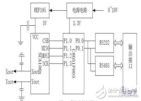
Figure 1 overall system block diagram
The angle measurement uses the silicon-based accelerometer SCA100t produced by VTI. Its main performance indicators are: 1) biaxial inclination measurement: SCA100t measures XY direction; 2) measurement range 1.7g; 3) measurement sensitivity 1.2V/g; 4) +5V single supply, two proportional voltage outputs (analog), built-in 11-bit AD converter; 5) SPI-compatible digital output; 6) internal temperature sensor via SPI interface.
The SCA100t is a 12-foot surface mount package. The chip should be mounted horizontally when designing, and the direction indicated by the arrow on the chip is positive. The output uses the SPI interface with a period of 19 clocks. Although the C8051F microcontroller has an on-chip SPI resource that does not match the SCA100t's SPI timing, the software analog SPI bus is used to read and write SCA100t data. The sensor also has an analog output interface, which is designed to lead out the two signals to meet the user's requirements. The data acquisition process uses Silicon's high-performance C8051F005 microcontroller as the main processor. It uses the CHP-51TM microprocessor core, which is fully compatible with the 8051, and has extended SPI, IIC AD and other peripherals on the chip. Instruction cycle with JTAG interface for direct debugging and programming. The industrial small sensor output interface generally uses RS-232C or RS-485 interface. Both interface circuits are designed at design time, and the user can select one of them to output data.
Dout is the digital output of the sensor; Sens is the sensitivity of the sensor, depending on the measurement range, 819 (4V / g) or 1638 (2V / g). The MCU reads the A/D conversion result of the two sensors in the SCA100t through the SPI port, and processes it in the MCU, and then outputs it through the serial port. At the same time, the internal temperature sensor is read out by the SPI interface to compensate the temperature of the measured value.
Improve accuracy measures
The SCA100t is very sensitive. The fluctuation of the power supply or the vibration of the device has a great influence on the accuracy of the output value. The temperature also has a certain influence on the output value. The welding surface may be uneven during soldering, installed in the casing or embedded in other parts. There may also be a certain angle with the reference plane in the system, which will cause the zero deviation of the measured value. Through experiments and analysis, the stability and reliability of the system are improved by the following methods:
Power supply circuit design
The unstable supply voltage can directly cause the proportional error of the output, and the maximum value can reach 2%. If the power supply is overloaded, the sensor is insufficiently powered and the output fluctuates. The system adds a power input protection circuit to prevent overloading the power input. The sensor is powered separately using the precision voltage source REF195, effectively reducing the effects of power supply fluctuations on the output. In the board design, 10nF filter capacitor is added between the sensor power supply and ground, and 10uF filter capacitor is added to the analog output, which can also reduce the ripple, thus reducing the output error; working in the embedded system At this time, the iron casing of this part of the circuit is electromagnetically shielded to reduce the influence of other working circuits or the surrounding environment. An array is set in the on-chip RAM of the microcontroller to store the solved angle value. The new measurement values ​​in the array are updated by the principle of the stack, and the data of the data is weighted and averaged and output. This can reduce the output fluctuation, but the output has a certain lag, and finally select 5 data processing through the experiment to meet the design requirements of the system. The output of the sensor is also affected by temperature. It has a temperature sensor inside and does not require temperature compensation in most cases. When the sensor is operating near the extreme temperature, it can be compensated by the MCU based on its internal temperature. The actual value of the temperature is calculated by:
The SCA100t also comes with an analog output that is more accurate than the 11BitAD conversion result of the SPI output. You can use the 12Bit or 16Bit AD chip or a higher precision AD microcontroller (such as C80051F060) to measure the voltage, and then calculate to get higher measurement accuracy. When the sensor is soldered or mounted, there are inevitably some tilt angles, resulting in zero error. After the sensor is fixed and fixed, it is calibrated on the 3D turntable to measure the zero error value in both directions and stored as a constant value in the Flash chip. The MCU subtracts the zero point error from the obtained measured value and outputs it, which basically eliminates the measurement error caused by the zero point error. After many experiments and improvements, the digital tilt sensor works reliably and stably, has high measurement accuracy, and is easy to be embedded in other measurement systems. It has been applied in many projects such as UAV attitude measurement.
iPhone 6S Plus Battery Pack, OEM Li-ion Polymer 3.8v 2750mAh with 1 year warranty. We are offered iPhone battery replacement is made from our own cell and customerized protection board,FPC and connectioner. Which is durable and safety,still keep 90% capacity more than 400 cycle times. iPhone Repair Battery daily production 100-150,000pcs,defective rate as 3‰.
iPhone 6S Plus Battery Pack
Nominal voltage: 3.8V
Limited charge voltage: 4.35V
Capacity:2750mAh (10.45whr)
Cell size: 29x49x119mm
iPhone 6S Plus Battery Pack,iPhone 6S Plus Battery Pack Replacement,Battery Pack For iPhone 6S Plus,iPhone 6S Plus Lithium-Ion Battery
Shenzhen Aokal Technology Co., Ltd. , https://www.aokal.com