Foreword
This article refers to the address: http://
In recent years, multi-function devices such as smartphones/tablets with high-performance applications have rapidly spread. Such a device that incorporates communication functions is prominently highlighted by diversity such as streaming, navigation, and cloud correspondence. In order to respond to the diversification of such functions and to realize a comfortable and fast communication method, it is a major issue to ensure communication capacity/communication frequency.
As a function common to communication terminals, we cite the correspondence of various networks here. The mobile communication standard is a 3G system UMTS (Universal Mobile Communication System) that realizes high-quality, high-speed data transmission based on the original GSM (Global System for Mobile Communications) 2G specification. In recent years, services called second-generation communication specifications such as LTE (Long Term Evolution) have also been introduced. LTE is a specification between 3G and 4G, also known as 3.9G, which is a communication technology that is expected to develop in the long run.
3G technology is only a speed of up to Mbps for uplink and downlink, but LTE has more than 50Mbps, and downlink speed of more than 100Mbps, reaching the same speed as fixed communication network. In GSM/UMTS-compatible terminals, there are usually four GSM carriers, and UMTS is equipped with 2-4 frequency bands. If LTE is required, 1-2 additional frequency bands will be added. FIG. 1 is a speculative diagram of the average number of frequency bands mounted in a mobile device. As the amount of traffic on the network increases, communication capacity and communication frequency are guaranteed, and the number of piggybacked LTE bands is expected to increase rapidly.
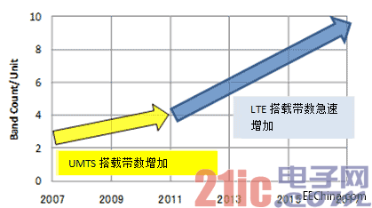
Figure 1: Estimation of the average number of bands carried in mobile devices
Shown in FIG. 2 is an exemplary diagram of a front end configuration of a GSM/UMTS/LTE corresponding terminal. In order to ensure high-quality communication quality, multi-function terminals are equipped, and in addition to these communication specifications, communication functions such as Wi-Fi, Bluetooth, and GPS are also widely used. It maintains the versatility and multi-band of mobile devices. In order to ensure the accommodation space within the volume defined by the product itself, the miniaturization of electronic components constituting the RF portion is also growing.
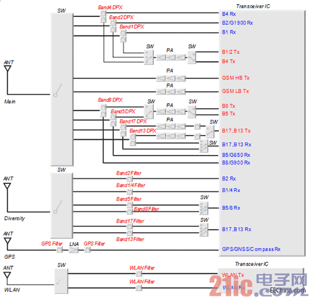
Figure 2: Example of front-end configuration of a GSM/UMTS/LTE-compatible terminal
Reduced capacity slimming in the front-end configuration section
The electronic components mounted on the front end portion of the mobile terminal are becoming smaller and smaller as the number of communication functions and the number of mounted frequency bands increase. While forming a wireless communication device, an RF transceiver IC (RFIC; radio frequency integrated circuit) is an essential component. The RFIC has the function of varying the frequency of the wave, adjusting and adjusting the signal. The trend of the input terminal of the receiving end of the RFIC is to convert the balanced input into an unbalanced input, and achieve the miniaturization of reducing the number of RFIC terminals by implementing signal processing of the unbalanced input. In addition, the signal strength of the PA is increased, and MMMB (Multimode Multi-Band) PA is used. If only a PA corresponding to one frequency band is used, it is necessary to install a PA with a number of bands, and MMMBPA corresponds to a multi-band, and one component can cover a plurality of frequency bands. If you use this, you can reduce the mounting area by reducing the number of components. Components such as inductors and capacitors are no exception, and can be miniaturized from 0603 size (0.6 x 0.3 mm) to 0402 size (0.4 x 0.2 mm).
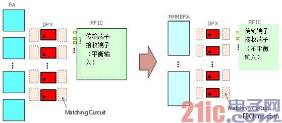
Figure 3: Cut-down of the front-end configuration section
The data is received and transmitted using different frequency bands, but to communicate at the same time, the duplexer is necessary in order to achieve the standard of receiving and transmitting the signal sub-band. The duplexer has different frequency bands, and can simultaneously filter the frequency of the transmission signal and the reception signal, and has a function of preventing the transmission circuit from flowing to the reception circuit. A SAW duplexer that combines the miniaturization and high attenuation of the duplexer has also been widely used. Its FDD method is the same as that of the duplexer, and the miniaturization of the SAW duplexer is more stringent.
Miniaturization of SAW duplexer
Figure 4 shows the changes in the size of the Murata SAW duplexer. From the size of the old cavity 3025 (3.0 × 2.5 mm), to the successful commercialization of the CSP model by establishing the resin sealing method, miniaturization was achieved. Later, by improving the electrode design and processing technology, we continued to improve the miniaturization. Thus, in 2013, the 1814 size (1.8 × 1.4 mm) CSP model SAW duplexer was successfully commercialized. It is 20% smaller than the current mainstream 2016 size (2.0 × 1.6mm), and it has become a new technology to support the increase in the number of bands to be mounted in the future.
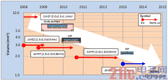
Figure 4: Product size trend
Table 1 shows a list of products of the 1814-size SAW duplexer currently being promoted by Murata.
The Band1.2.5.8 global band has been prioritized for productization, and the LTE band has also expanded its product lineup, which is expected to be launched from the end of 2013. Due to the small frequency separation between the output frequency band and the receiving frequency band, products such as Band2.3.26 with high difficulty are successfully commercialized by using LowTCF technology. In addition, the unbalanced flow direction of the receiving terminal of the RFIC is met, and the duplexer of the unbalanced model of the receiving port achieves the priority enrichment effect.
Table 1: Product overview of the 1814 size SAW duplexer (expected)
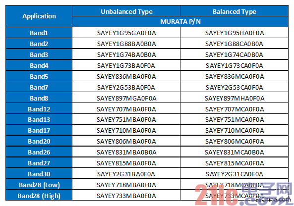
Figure 5 shows a comparison of the transmission characteristics of the 2016 size and 1814 size duplexers for Band7. In order to coexist with the Wi-Fi system, it is necessary to improve the size of the Band7 duplexer 2016 with high attenuation in the Wi-Fi band. The transmission characteristic of the transmission side is a target of high attenuation in the Wi-Fi band and low insertion loss of the Band 7 transmission band. Despite the limitations of the 1814 size miniaturization design, we paid attention to the comfort of the electrode design and spent enough time on the chip layout, so the Band7's features surpassed the 2016 size.

Figure 5: Comparison of features between 1814 size duplexer and 2016 size duplexer (Band7)
Future prospects
List two future prospects.
Expansion of module products
With the further development of miniaturization and multi-banding of mobile terminals, miniaturization and compositing of components to be mounted in the future will become necessary conditions. The reduction in the mounting area achieved by the miniaturization of discrete device products has reached the limit, and modular components such as PA/SW/matching elements of peripheral products will become essential products in the future. Murata has successfully developed a product that has been miniaturized even with a mold size through the unique construction of modular products, and has advanced the miniaturization of module products.
Multiplexer expansion
The module terminal further realizes high-speed communication, and the application of the LTE development situation "LTE-Advanced" has also begun. Because of the implementation of high-speed communication, multiple frequency bands are simultaneously utilized, and a CA technology that measures the bandwidth of the communication band can be introduced. As a problem, the bandwidth combination of Low-Low and High-High is not easy to implement. As a solution to this problem, we are developing a four-channel multiplexer that connects two duplexers in one input port as shown in FIG. 6. In addition, the integration of the two duplexers into one product achieves a reduction in the mounting area, and it is expected that the front end portion will be slimmed down. In the future, Murata will develop a multiplexer such as a four-channel multiplexer and a three-way (duplexer + single filter).
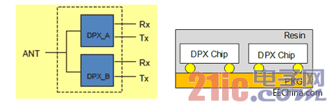
Figure 6: Quad Channel Multiplexer
Double Burner Electric Hotplate
Double Iron Hotplate,Double Burner Electric Hotplate,220V Hotplate,Double Burner Hot Plate
Shaoxing Haoda Electrical Appliance Co.,Ltd , https://www.zjhaoda.com