LEDs are looking for ways to expand their range of applications. Automotive lighting, TV backlights, and tablets are just a few of the applications that require multiple LEDs. Driving a large number of LEDs with a constant current can be done over a long serial connection or by driving multiple LED strings in parallel. However, connecting a large number of LEDs to a long string can cause high voltage and single point of failure problems. Similarly, powering multiple strings in parallel requires multiple current regulators, one for each string, which can result in higher complexity and cost. The current trend is to have multiple series and parallels working. This article will explore the methods and principles for implementing circuit systems to achieve this goal.
Similar to standard diodes, LEDs are also current-driven devices. It has an IV curve where the current and voltage are non-linear and a small change in forward voltage results in a large current change. Since the LED current is almost proportional to the LED luminous flux, it is important to accurately control the current for applications such as television. But not all applications must require high precision for LED brightness matching. If the LEDs are driven in a single string, the brightness will definitely match because each LED has the same current intensity. As the number of LEDs used increases, parallel strings must be used and the choice of how to control each string of current must be made.
A typical white LED has a forward voltage of 3.3V and a variable of up to 20% at rated current. If 10 LEDs are used in series, then at the same current, the first string may require 33V to fully drive, while the second string requires 39.6V. If these two strings are connected in parallel, the current of the lower voltage string shunt is significantly more than expected, while the second string is significantly less. It is less likely that all LEDs in a single string will be at the high end of their forward voltage specification, and the more LEDs used, the less likely this is.
In fact, the balance between the two strings is much better, but there may still be a few volts. To help with this situation, LED manufacturers use the binning method to group components that accurately match the LED forward voltage (Vf) voltage drop (and flux and wavelength) for better performance. Figure 1A is a simple, low-cost implementation of dual-parallel implementation that requires only a fixed voltage supply and a simple resistor to set the current strength.
The voltage across the sense resistor can be adjusted by an external control circuit to achieve precise control of the LED current by turning the output voltage up or down. Although this adjusts the LED current in the first string, it does not necessarily work in the second string. If the control loop can increase the output voltage of the regulated LED string, but the voltage drop of the second string is lower in both, it will make the current of the second string worse.
When applied to a standard diode, the LED forward voltage drop decreases with increasing temperature. If one string is much hotter than the other, its forward voltage drop will decrease and begin to consume more current. This increased heat dissipation further increases the temperature, which not only increases its current, but is also likely to cause LED failure due to thermal runaway. In this case, it is required to drive the voltages of the strings through current regulation and keep them constant. In addition, all LEDs should be mounted on a common heat sink to maintain the same possible operating temperature between them.
Thermal runaway is not a problem when driving strings with a constant voltage, but the current matching between strings is poor. Since each string is independent of each other (ie, the current in one string does not directly affect the current in the other string), the fault tolerance is better when driving with a voltage source, but the current in one string is passed through Vfb. When adjusting, the fault tolerance is not good. In this case, if an LED is turned on in the regulated string, the voltage driving the strings can be increased by the control circuit and eventually cause an overvoltage in the unregulated string, causing a malfunction. The circuit in Figure 1A does not provide accurate LED string current matching for more demanding applications when a non-feedback voltage supply is sufficient to meet demand.
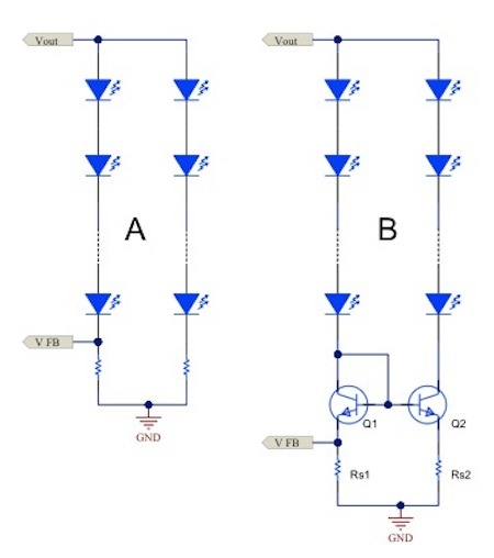
Figure 1. The current mirror (B) offers various advantages for simple resistor current regulation (A).
Figure 1B uses a current mirror to regulate the current in the two strings. The first string not only uses the voltage feedback (Vfb) from the sense resistor Rs1 to regulate its current, but also sets the same voltage in Rs2 depending on the Vbe match of Q1 and Q2. With the same sense resistor voltage value, the same current can be forced into the second string. The accuracy of the adjustment depends mainly on the match between the Q1 and Q2 Vbe voltages. To this end, providing a two-way resistor that supports two components on the same die can help reduce temperature, processing, and other variations.
This circuit provides the proper accuracy, but the basic current mismatch and the ratio of Vbe to Rs create errors that make it less than perfect. The larger the ratio of Vfb voltage to Vbe, the lower the error, but it will increase power consumption. In addition, adding a series-connected base resistor to Q1/Q2 may also help improve accuracy.
See the original text : http://
The Texas Instruments Online Technical Support Community provides technical support to Chinese electronics engineers to answer technical challenges. The German instrument community involves analog electronic technology, microcontroller, MCU, embedded system, DSP, digital signal processing, and is the preferred technology exchange platform for electronic engineers using TI chip design. For more forums, please visit: http://
Smart meter is one of the basic equipments for data acquisition of smart grid (especially smart distribution network). It undertakes the task of collecting, measuring and transmitting raw energy data, and is the basis for information integration, analysis optimization and information presentation. In addition to the metering function of the basic power consumption of the traditional electric energy meter, the smart meter has two-way multi-rate metering function, user-side control function, and two-way data communication in various data transmission modes in order to adapt to the use of the smart grid and new energy. Intelligent functions such as function and anti-stealing function
Meter Pcb,Pcb Circuit Boards,Pcb Circuit Board For Meter,Multilayer Printed Circuit Board
Chuangying Electronics Co.,Ltd , https://www.cwpcb.com