3G is a third-generation mobile communication technology that combines wireless communication technologies and multimedia technologies such as the Internet. With the development of 3G technology, it has greatly improved the speed of transmission of sound and data, and can achieve wireless roaming on a global scale. The advantages of high speed data transmission, always online, wide coverage, etc., effectively solve the bottleneck problem of information transmission and control distance brought by mobile robots using wired or wireless remote control, so that remote rescue robots, simulation robots, and families Mobile robotics such as babysitting robots have an available solution for real-time transmission of large data volumes.
1 system overall architecture
The system is mainly used to transmit the video data collected by the mobile robot to the server through the 3G network, and then transmit the control signal of the server to the motor drive board to drive the movement of the mobile robot platform. The overall architecture is shown in FIG. 1 . The video image captured by the camera OV9650 is compressed by JPEG and stored in the buffer area. When the server listens to the client's access request, the data of the buffer area is transmitted to the monitoring interface of the client through the network for display; when the robot action needs to be controlled The control button of the client sends control information to the server, and the server controls the underlying motor driver through the program parsing to drive the robot platform to move.
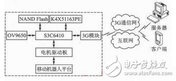
Figure 1 Overall architecture of the system
The system hardware platform core processor adopts S3C6410, which is based on ARM1176JZF-S core. It is a 16/32-bit RISC microprocessor, which integrates powerful hardware accelerators, including audio and video processing, 2D acceleration, etc., 2.5G and 3G communication services provide optimized hardware performance up to 677 MHz; 2 GB NAND Flash for kernel code, applications, file systems and data; DDRSDRAM with two 128 MB K4X51163PE chips; camera With CMOS image sensor OV9650, the maximum output is 1.3 million pixels (1300 & TImes; 1 024), with high sensitivity, low power consumption, support for a variety of commonly used image format output, support for automatic image control and so on.
As a Unix-like operating system, Linux has the characteristics of stable and robust, low cost, high performance, good interoperability and open source code. Its good core structure and tailorable features meet the diverse needs of embedded applications, making it a place in the embedded system field. The Linux kernel used in this system is version 3.0.1, the file system uses YAFFS2, and the bootloader uses uboot.
2 system software design
2.1 Video data collection and transmission
The acquisition of video data is done by the driver of the video device OV9650 in Linux and the corresponding interface provided by Video for Linux. For convenience, the information about video capture is encapsulated into the following structure:
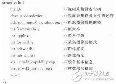
The acquisition program completes the initialization of the camera and the acquisition parameters through the function init_s3c6410 (struct vdIn*vd, char*device, int width, int height), and captures the image through the function s3c6410_Grab (struetvdIn*vd), compressing with JPEG The algorithm compresses the acquired image in an image format of RGB565.
The video data transmission is realized by Socket, and is directly transmitted between the server device end and the web client, and the video switching control is realized by the video stream server. Since video transmission is a continuous process, both the client and the server implement transmission and reception through threads. The receiving thread is created by the function pthread_create(& (servers[id].threadID), NULL, server thread, &(servers[id])).
Video capture and transmission is implemented in two threads, which share a buffer pool. Both threads are created and run when the program on the video capture server is started. The thread that collects the video image continuously collects the live image through the camera, and is stored in the buffer pool after being compressed by JPEG, and the thread transmitting the video data creates a Socket to listen for the connection request waiting for the remote client. When a client sends a connection request and establishes a connection, the video data is sent to the remote client through the connection, and the transmitted video data is obtained from the buffer pool. That is to say, on the video collection server side, everything needed for video data transmission is ready, waiting for the client's request, once the connection is established, the video data can be sent, thereby achieving faster speed and higher efficiency. .
The working flow chart of video capture and transmission is shown in Figure 2.
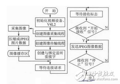
Figure 2 Working flow chart of video capture and transmission
The electrolyte material inside the Electrolytic capacitor, which has charge storage, is divided into positive and negative polarity, similar to the battery, and cannot be connected backwards.A metal substrate having an oxide film attached to a positive electrode and a negative electrode connected to an electrolyte (solid and non-solid) through a metal plate.
Nonpolar (dual polarity) Electrolytic Capacitor adopts double oxide film structure, similar to the two polar electrolytic capacitor after two connected to the cathode, the two electrodes of two metal plates respectively (both with oxide film), two groups of oxide film as the electrolyte in the middle.Polar electrolytic capacitors usually play the role of power filter, decoupling (like u), signal coupling, time constant setting and dc isolation in power circuit, medium frequency and low frequency circuit.Non-polar electrolytic capacitors are usually used in audio frequency divider circuit, television S correction circuit and starting circuit of single-phase motor.
Electrolytic capacitor
Electrolytic Capacitor,Aluminum Electrolytic Capacitor,High Voltage Electrolytic Capacitor,12V Electronic Components Capacitor
YANGZHOU POSITIONING TECH CO., LTD , https://www.yzpstcc.com