introduction
This article refers to the address: http://
Public transportation has the strong advantage that individual transportation can't match. Giving priority to the development of urban public transportation system is the best way to solve the traffic problems in large and medium cities. In recent years, the intelligentization of urban public transport systems has become the main direction of public transport research. Most of the existing trial-run intelligent public transportation systems in China use GPS global positioning system for positioning, and GPRS network is used for data transmission. The vehicle GPS module can acquire navigation and positioning data such as position, direction and time in real time, and then transmit the data to the monitoring center through the vehicle GPRS module, thereby realizing the positioning and monitoring of the vehicle. The monitoring center can send the real-time information or announcement information of the vehicle to the electronic station card through the GPRS module of the electronic station card to estimate the arrival time and distance, and then display on the electronic station card. Although the existing trial-run intelligent public transportation system has a wide coverage and high precision, it can realize the full range of positioning and monitoring of the vehicle. However, in the actual operation process, the following deficiencies still exist:
GPS signals will have blind spots in tunnels and viaducts;
During operation, the GPS information needs to be sent to the monitoring center via GPRS, and then the monitoring center sends the display information to the electronic station card through GPRS, so the operating cost is high;
The GPRS module is expensive, the number of buses is large, and the GPRS module must be installed, and the hardware cost is high;
It is impossible to realize the communication between the bus and the stop sign, and it is also impossible to realize the services such as early reporting.
1 system overall plan
Due to the small size of Xi'an city, the concentration of roads and the dense bus lines, the distance between electronic stop signs is mostly around 500 meters. Therefore, it is not necessary for the monitoring center to monitor the bus in real time, but only need to know the stop sign of the bus. The range can be roughly positioned.
In order to absorb the advantages of the existing intelligent public transportation system scheme, overcome its shortcomings, and combine the characteristics of Xi'an city, this paper introduces ZigBee short-range wireless communication technology into the intelligent public transportation system, which is widely used in the existing trial-run intelligent public transportation system in China. The GPS positioning and GPRS information transmission scheme improves the data transmission mode. The overall architecture of the improved intelligent public transportation system scheme is shown in Figure 1.
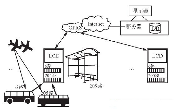
Figure 1 Overall plan of the intelligent public transport system
The system is mainly composed of three parts: bus terminal, electronic station terminal and management monitoring center server.
The bus terminal can locate the position information of the bus in real time according to the vehicle GPS module, and compare with the position information of each station card. When it arrives at a certain stop sign, the bus automatically announces the station and displays the station with the LCD screen. information.
The electronic station terminal and the bus terminal can communicate via the ZigBee short-range wireless communication network. Buses can be used to report in advance. When the bus arrives at a stop sign, it sends its own vehicle information, status information, etc. to the stop sign. After receiving the information of the management center, the electronic stop sign displays the location information of the bus on the electronic map of the stop sign.
The management center server and the electronic station terminal can communicate via the GPRS wireless communication network. The electronic station terminal is wirelessly networked through the GPRS module to process and re-enclose the received bus information and then transmit it to the wireless network. The server side is generally a PC connected to the Internet, and can receive information on the Internet through the TCP/IP protocol, and can also send real-time location information and announcement information of the bus on the running line to the electronic station terminal. The server can manage and query information through the database to facilitate the management and scheduling of the bus company.
2 system hardware design
2.1 Hardware components of the vehicle terminal
The vehicle terminal hardware in this system mainly includes power module or power access module, ARM processor, RAM, FLASH, GPS positioning module, ZigBee RF transmission module, video monitoring module, LCD display module, serial port and debugging module, number of people in the car. Statistics module and voice module. Figure 2 is a block diagram showing the hardware components of the vehicle-mounted terminal in the system.
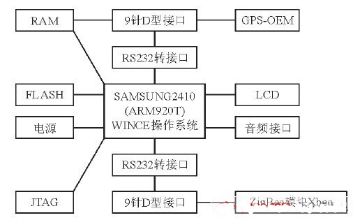
Figure 2 Block diagram of the hardware components of the vehicle terminal
The ARM embedded processor is the core of the entire vehicle terminal and can be connected to each functional module through various interfaces. This car terminal uses a 16/32-bit RISC embedded microprocessor based on the ARM920T core of South Korea's Samsung 802C. The S3C2410.S3C2410 can run at 203 MHz, which is mainly for cost-effective and low-power applications such as handheld devices.
In the intelligent public transportation system, the system positioning module generally uses a GPS-OEM (Original Equipment Manufacture) board.
In the embedded vehicle terminal system, when the GPS module is selected, several factors such as positioning accuracy, price, power consumption, volume, and anti-interference ability should be considered. According to the above principles, this design uses LEADTEK's GPS three-generation SiRF star III7855 module to achieve positioning. The main performance indicators of this module are as follows:
There are 20 parallel channels that can receive 20 satellites simultaneously;
Positioning time: Recapture time is 0.1 s, hot start <1s, cold start <42 s, automatic search less than 30 s;
Output differential accuracy up to 10 meters, power consumption is less than 1 W;
The ASCII code statement of the NEMA-0183 protocol can be output through the RS232 interface, including GPGGA, GPGSA, GPGSV, GPRMC, GPVTG, GPGLL, etc.
With a 5 V Power Supply, a DB9 interface can be connected via the TX and RX pins to communicate with the serial port of the embedded microprocessor.
2.2 ZigBee RF Module
In the intelligent public transportation system, the GPS module only completes the information collection function, and when the bus arrives at the station, it also needs to send the station card through the ZigBee module information.
After market research, Freescale's MC1319x platform has low power consumption, low price, high hardware integration, and is convenient for secondary development. The stability of the RF communication system is also relatively high. Therefore, this design uses MaxStream's ZigBee-compatible XBeePro RF module with the Freescale MC1319x chipset as its core. The XBee Pro module is designed to meet the IEEE802.15.4 standard and operates at 2.4 GHz. The basic performance parameters are as follows:
â—‡ Transmit power l00 mW;
â—‡ The indoor transmission distance is 300 m, and the outdoor transmission distance is 1500 m;
â—‡ RF data transmission rate is 250 kbps;
å‘é€ With a 3.3 V supply, the transmit current is 215 mA and the receive current is 55 mA.
Figure 3 shows the pinout of the XBee Pro module, which has 20 pins. The pins of the RS232 interface board can be connected to the VCC, GND, DOUT, and DIN pins. VCC is the power supply pin (2.8~3.4 V); GND is grounded; DIN is the signal input pin, which can be used as UART data input, usually connected with the UART receiver TX of the processor; DOUT is the signal output pin, which can be used as UART Data output, usually connected to the processor's UART receiver RX. In addition, a UART interface is integrated in the XBee/XBee Pro module. The internal data control flow of this interface is shown in Figure 4.
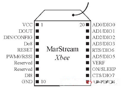
Figure 3 Pinout diagram of the XBee Pro module
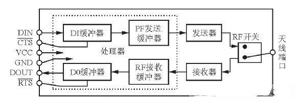
Figure 4 UART internal data control flow of XBee Pro module
When the serial data enters the XBee Pro module through the DIN pin, the data is stored in the DI buffer until it is sent out by the transmitter through the antenna; when the RF data is received by the antenna, the received data enters the DO buffer until it is deal with. Under certain conditions, the module may not be able to process the data in the serial receive buffer immediately. If a large amount of serial data is sent to the module, it may be necessary to use CTS flow control to avoid serial receive buffer overflow. The XBeePro module can be directly connected to the UART interface of the controller through the UART interface. The hardware interface is simple and practical.
2.3 Hardware composition of the electronic station terminal
Compared with the bus vehicle terminal, the hardware component of the electronic station terminal is mainly replaced by the GPS positioning module on the bus to the GPRS-DTU data transmission unit. GF-2008AWGPRS-DTU is a GPRS wireless data communication product developed and produced by Beijing Jiafuxin Technology Co., Ltd. The built-in Siemens MC39i GPRS module has the characteristics of high accuracy, good environmental adaptability, easy installation and maintenance, and can be used for users. Provide high-speed, reliable, always-on data transmission services and virtual private data communication network services, which can be widely used in remote meter reading, environmental data collection, traffic information release and other aspects. The following are the main features of GF-2008AW GPRS-DTU:
It can realize transparent wireless data transmission of serial port, and it is stable and reliable;
Highly integrated GPRS and TCP/IP technology to combine the Internet and wireless networks organically;
Support a variety of TCP / IP protocols, such as TCP, UDP, DNS, PPP, RAS, etc.;
According to the flow rate, no traffic is not charged;
Smallest in standard RS232 interface products, suitable for embedded integration;
Support peer-to-peer, point-to-multipoint, center-to-multipoint peer-to-peer data transmission;
The AT+i command interface based on serial communication can save development time and development cost;
With ALWAYS ONLINE mode, disconnection can be automatically redialed;
It is powered by 5~24 V / 1 A and has an energy saving mode.
3 ZigBee communication program design
3.1 ZigBee networking solution
Since there are usually multiple buses arriving at the station at the same time, one stop number corresponds to multiple buses. In view of the small number of network nodes and the relatively simple network structure, the system adopts a star model networking.
That is, the electronic station card distributed on the bus line is configured as a ZigBee coordinator, and the arriving bus is configured as a ZigBee terminal device. Figure 5 shows the networking mode of the bus and the stop sign. When the ZigBee network coordinator on the station selects a channel and PAN ID and starts up, a ZigBee Personal Office Network (PAN) is established.
Once the coordinator starts the PAN, the router and the terminal device node are allowed to join the PAN. When the vehicle terminal that is the ZigBee terminal device joins the PAN, the system will receive a 16-bit network address, and simultaneously send and receive from the ZigBee coordinator. The data of the electronic terminal terminal. The network address of the PAN coordinator is always 0. Since the network physical address of the ZigBee module on the station is unique, the information can be sent to the station through the physical address.
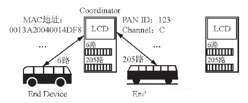
Figure 5 Bus and station network
3.2 API operation of ZigBee module
XBee Pro has five operating modes: empty mode, receive mode, transmit mode, sleep mode, and command mode. For each mode of operation, there are two modes of operation, transparent mode and application program interface (API) mode. When working in transparent mode, the module can replace the role of the serial line and operate various information in bytes; when working in the API mode, all data of the incoming and outgoing modules are included in the operation and events of the defined module. In the frame structure. This article uses the API operation mode.
API operations require modules to communicate through a structured interface (data communicates interactively through a sequence of defined sequences). The API specifies command transmission, command response, and transmission and reception of module status information through serial data frames.
(1) ZigBee sends a request
After the bus arrives at the stop sign, it should send the date, time, car number, bus line, number of people in the car, driving direction and other information to the electronic station card according to the MAC address of the station sign. The API frame structure definition of the bus ZigBee module transmission mode is shown in Figure 6. Among them, Bytes6-13 is the MAC address of the stop sign.
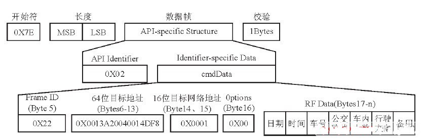
Figure 6 Bus TX request API frame structure
(2) ZigBee transmission status
In order to achieve reliable transmission, after the bus transmits the information to the electronic station card, the confirmation message of the electronic station card must be obtained, so the transmission status information of the electronic station card to the bus must also be obtained. This information will indicate whether the packet was successfully sent or failed to be sent. If the transmission fails, the bus information must be resent until the transmission is successful.
The electronic station card continuously sends information to the PAN according to the MAC address of the bus, and determines whether there is a bus to join the network by reading back the transmission status. If so, the bus is identified according to the network address, and the bus is located. Information is sent to the monitoring center to complement the GPS positioning method.
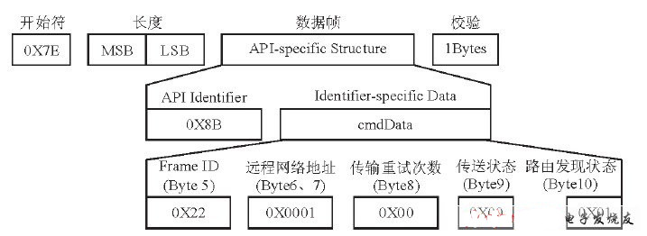
Figure 7 shows the TX status frame structure of the bus ZigBee module.
Among them, Bytes 9 is the transmission status information, and Bytes 6 and 7 are the 16-bit network addresses of the receiving module.
(3) ZigBee receiving package.
The electronic station card is parsed after receiving the status information data packet sent by the bus, and is sent to the monitoring center through the GPRS module of the station card. The definition of the API frame structure of the receiving mode of the ZigBee module of the electronic station is as shown in FIG. 8. The Bytes 5-12 in the figure is the MAC address of the bus.
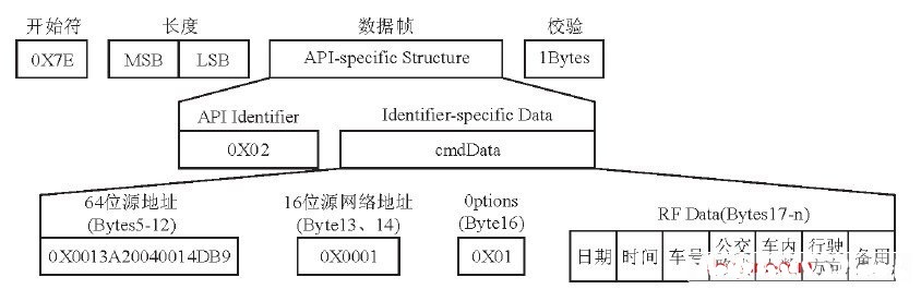
Figure 8 API frame structure diagram of the electronic station RX
3.3 GPRS network communication design
After receiving the information sent by the bus, the electronic station will send it to the monitoring center via GPRS-DTU, and then the monitoring center will send all the information sent by the bus to the station through the Internet.
The GPRS DTU has five modes: transparent transmission mode, AT+i command mode, automatic IP registration mode, remote maintenance and flow control. In the system's electronic stop terminal, the DTU will use the transparent transmission mode to interact with the server for information. Through the transparent transmission mode, the asynchronous serial communication of the electronic station can be converted into network communication based on the TCP/UDP protocol. Its main purpose is to achieve communication over an IP network through a simple device for serial communication without any change in the data format. This is very important, because the data format does not change before and after DTU, so the original equipment and software of the electronic station can be directly applied without any upgrade.
The DTU's transparent transmission mode enables the electronic station client to establish a network connection with the server when initiating a communication request. That is to say, when the electronic station card lower computer and the server perform data transmission, the first is that the lower station of the electronic station card is connected to the serial port of the DTU device, and is automatically called after the DTU enters the transparent transmission mode, and establishes a network connection with the server. After the network connection is established, the DTU will automatically complete the serial-to-network communication conversion so that all data can be transparently transmitted between the server software and the electronic station lower-level machine.
Communication between the server and the electronic station terminal can be achieved through a Socket socket. First, create a listener Socket object on the server, and bind it to a fixed port. Then, whenever the electronic station client sends a SOCKET connection request, the server will open a new thread and create a socket in it. The socket communication of the electronic station client, until the electronic station client program is closed, the thread ends, and then the socket of the server main thread is closed when the application exits. Through multi-threaded Socket programming, one server can communicate with multiple electronic station clients.
The following is the specific implementation code of the server based on socket multithreading:
DWORD WINAPI AnswerThread ( LPVOIDlparam) / / send and receive thread entry
{//When creating a thread, pass the new socket created by the server to lparam
SOCKET ClientSocket = ( SOCKET) ( LPVOID) lparam;
Int bytesRecv;char sendbuf [ 32] = " " ;char
Recvbuf [32] ="" ;
While (1)
{bytesRecv=SOCKET_ERROR;
For ( int i =0;i < ( int) strlen ( recvbuf) ;i ++ )
{recvbuf [i] =' ';}
While (bytesRecv==SOCKET_ERROR)
{ bytesRecv =recv ( ClientSocket,recvbuf,32,0) ;} //5 Receive data from the electronic station client
...
Send ( ClientSocket, recvbuf, strlen ( recvbuf) , 0) ; / / 6 send data to the electronic station client
}
}
...
WSAStartup (MAKEWORD (2,2),&wsaData) ;//Initialize Winsock
Socket ( AF_INET, SOCK_STREAM, IPPROTO_TCP) ;//1 create a listening socket
Bind ( m_socket, ( SOCKADDR*) &service,sizeof(service)) //2 binding socket
Listen (m_socket, 20) //3 listening socket
SOCKET AcceptSocket;
While (1) / / has been waiting for the client's request, after the request comes, create a new connection socket
{ AcceptSocket=SOCKET_ERROR;
While (AcceptSocket==SOCKET_ERROR)
{ AcceptSocket =accept ( m_socket, NULL, NULL) ;} /*4 Wait for the client request to arrive. After the request arrives, accept the connection request and return a new socket*/ for this connection.
hThread =CreateThread ( NULL,NULL,AnswerThread, ( LPVOID) AcceptSocket,0,&dwThreadId) ;} /*Create a new thread, pass the new connection socket to the AnswerThread entry function */
}
4 Conclusion
In this system, the bus and the electronic station card realize information exchange through the ZigBee network, and the electronic station card and the monitoring center realize information interaction through the GPRS network. The low-cost ZigBee module on the bus replaces the in-vehicle GPRS module in the existing intelligent bus system, which can save hardware costs, and the ZigBee network communication between the bus and the electronic station can realize the positioning of the bus as a GPS. The addition of positioning increases the reliability of the system.
In the future, with the maturity of wireless communication technologies such as 3G, WiMAX, Wi-Fi and the emergence of more optimized satellite positioning technology, more and more intelligent public transportation system solutions will emerge, thus promoting the intelligent public transportation system to a greater extent. development of.
Muti USB Charger means the charger with over 2 usb ports, you can use it to charge more usb devices at the same time. Multi-port Adapter power up your mobile phone, tablet, e-reader, Bluetooth headphones, portable speakers and nearly any usb devices.
Yidashun offer Multiple USB Charger with type-c port, or QC 3.0 port, which can charge the phones fast with quick charge support like iphone 8, and yidashun also offer car mutiple usb charger so that people can charge mobile phone or other devices in the car.


Multi USB Charger,Multi Port USB Charger,Portable Multi USB Charger,Quality Multi USB Charger
Shenzhen Yidashun Technology Co., Ltd. , https://www.ydsadapter.com