Application area: automotive electronics testing
This article refers to the address: http://
Challenge : The function test of the oil pump needs to test the performance of the oil pump bracket, and the test system is required to have good reliability and timeliness. The testing process includes not only the control of multiple instruments but also the content of data acquisition and motion control. Therefore, it is necessary to establish a system for multi-functional test development, and the system must have good reliability and timeliness.
Application scheme: The oil pump bracket function test bench is mainly used for testing various performances of the oil pump bracket, including a series of liquid level resistance (TSG resistance), oil pump starting current, CO resistance, DRV resistance, oil pump rotation polarity and system barcode. key parameter. The accuracy of the test results will directly affect the factory specifications and quality of the pump support system. The testing of these parameters requires not only the high precision and high real-time performance of the test system, but also the high reliability and anti-interference ability of the equipment.
The COMPACTRIO test system is an FPGA-based, low-reliability, high-accuracy test system that was developed by National Instruments (NI) for testing requirements under complex environmental conditions in industrial applications. The system is especially suitable for industrial environments where the relative environment is poor, and the test reliability and real-time high. Compared with the traditional PCI or PXI capture card system, it has high reliability, high precision, high real-time, high cost performance, and is not limited by the occasion and location. Compared with the traditional PLC system, it has a series of advantages such as fast response and more flexible acquisition and control. It is foreseeable that the FPGA-based COMPACTRIO test technology will bring a new test theory to industrial test situations, and it will have an important and far-reaching impact on industrial test technology.
Products used:
LabVIEW2009 SP1 RT FPGA
NI cRIO-9074
NI 9205
NI 9411
NI 9401
NI9476
NI 9425
NI 9870
text:
1 Overview *
The XLM2 line function test bench is mainly responsible for testing the performance of the oil pump bracket assembly. It is mainly tested for the oil pump bracket system of GM and Ford's 12 models. The main test parameters include: oil body float level resistance (TSG resistance), oil pump starting current, CO grounding resistance, DRV grounding resistance, oil pump rotation polarity and product barcode scanning and other key parameters. The test results are directly related to the factory specifications and product quality of the oil pump bracket system. The function test bench is extremely important in the final inspection of the entire production line.
In response to the above test requirements, if the traditional PCI-based data acquisition test system is used for development, it is greatly affected by the host computer operating system and the test environment. The development based on PLC is limited by conditions such as acquisition speed. Therefore, this article uses the latest COMPACTRIO test technology developed by National Instruments (hereinafter referred to as National Instruments) in recent years. It is a technology based on the underlying FPAG programming, including a real-time controller and reconfigurable FPGA chip, the bottom layer. The hardware resources are open to users, avoiding the limitations of the software operating system and the inherent acquisition mode, and have good flexibility and reliability.
2 test system functions and hardware architecture
The oil pump bracket function test bench is shown in Figure 1.
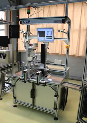
Figure 1 Oil pump bracket function test bench
The test function of the test bench can be divided into 3 basic parts.
1) Equipment instrument control
Including TSG resistance test drive servo motor control, scanner control and polarity detector control.
The TSG resistance test requires that the control motor be under constant speed conditions. The whole process is divided into three stages, as shown in Figure 2.
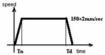
Figure 2 TSG resistance test process
2) Analog signal acquisition
Includes measurements of TSG resistance, CO resistance, and DRV values.
3) I/O control
Including negative pressure suction cylinder, CO probe cylinder, DRV push-up cylinder, DRV probe cylinder and multiple relays for signal output control, and at the same time identify the photoelectric switch, height upper and lower limit proximity switch, zero proximity switch, safety The relay and the two-hand controller perform input signal capture.
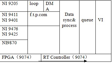
Test system architecture:
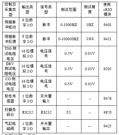
Due to the large number of functional test types of this system, it is difficult for a single data acquisition device or I/O control device to meet the requirements. After many comparisons and selections, the test system uses NI's latest COMPACTRIO test technology, based on the low-level FPGA programming NI cRIO-9074 system architecture. The system architecture is shown in Table 1.
Its system hardware is shown in Figure 3:
Figure 3 cRIO-9074 test system
The function of each module and the analysis of the collection amount are shown in Table 2:
The electrical wiring of the system wiring is shown in Figure 4:
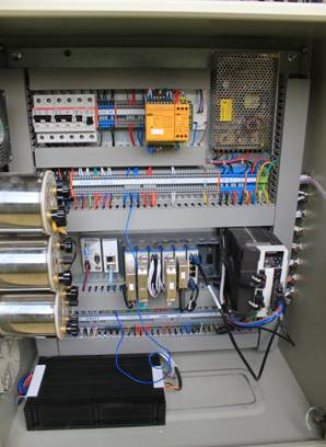
Figure 4 System wiring physical map
3 test system software components
The software interface of the system is shown in Figure 5.
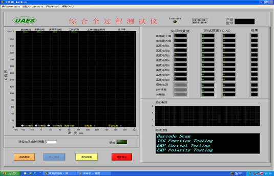
Figure 5 test system software test interface
Its operation function is shown in Figure 6.
Figure 6 system test function
3.1 Automatic test function. The system has an automatic test function, and its detailed test process is as described in 4.
3.2 Manual test function. As shown in Figure 7. The system has manual control of the test motion control components, which can be manually adjusted for all motion control to facilitate system debugging.
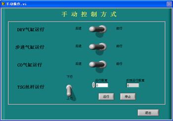
Figure 7 manual function test interface
3.3 Verification function. Since the test system runs on the production line for a long time, the stability and accuracy of the test is very important. The test system software is designed with photoelectric switch calibration, height check, TSG resistance check, DRV resistance check, CO resistance check, start current check, polarity check. The system is periodically verified through the corresponding operation interface to ensure the reliability of the system for long-term testing.
3.4 Test workpiece parameter selection. The system sets various types of production line test workpiece types inside the system. By testing the workpiece selection, the test parameters will be automatically loaded into the test interface.
3.5 Test data records. After the workpiece test is completed, the data during the test will be automatically recorded and saved.
4 system automatic test process
The system automatic test process is shown in Figure 8.
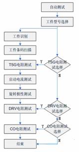
Figure 8 system automatic test process
1) Workpiece identification. When the workpiece is normally loaded into the test fixture, the system will automatically identify the workpiece and judge whether it is qualified. If the workpiece is correctly identified, the next process test is performed. If no workpiece is placed, or the workpiece is placed in the wrong position, the system automatically prompts the workpiece to recognize the error alarm and stop the test. Manual reset is required and the test is restarted.
2) Scan barcode identification. When the workpiece is identified, the scanning barcoder automatically opens the barcode scanning of the test workpiece. If the scan code is consistent with the preset scan client code, the system automatically determines that the scan bar code is acceptable, closes the scan bar code, and performs the next process test. If the scan code is inconsistent with the preset scan client code, the system automatically prompts for a scan bar code error alarm and stops the test. Manual reset is required and the test is restarted.
3) TSG resistance value test. When the workpiece bar code is scanned, the system will determine whether to perform the TSG resistance test according to the model selection. If the TSG resistance test is selected, the system will automatically perform a TSG resistance test. Otherwise, the system will skip the test procedure and test the next process.
During the TSG resistance test, the system will control the motor test lead to drive the float of the workpiece to be tested for TSG resistance, and record the test curve with the height as the abscissa and the test resistance as the ordinate. , compared with the pre-set inspection range. As shown in Figure 9.

Figure 9 TSG test curve and inspection range window
If the test point test results are within the test range, then the TSG resistance test is judged to be qualified, and the next process test is performed. If one or more of the test data exceeds the inspection range, the system automatically prompts the TSG resistance test error alarm and stops the test. Manual reset is required and the test is restarted.
4) Start the current test. After the workpiece TSG resistance test is passed (if the system chooses to perform TSG resistance test), the system will automatically turn on the test power supply, perform the workpiece start current test, and compare the maximum value of the start current with the preset allowable maximum start current. If the test result is less than the preset value, it is determined that the start current test is qualified, and the system automatically performs the next process test, otherwise the system automatically prompts to start the current error alarm. Manual reset is required and the test is restarted.
5) Polarity test. When the start current test is passed, the system will turn on the polarity sensor and perform the polarity test under the working conditions of the workpiece. If the workpiece works normally, the polarity test is qualified, and the system automatically performs the next process test, otherwise the system automatically prompts the polarity error alarm. Manual reset is required and the test is restarted.
6) DRV resistance test. When the polarity test is passed, the system will determine whether to perform the DRV resistance test according to the model selection. If the DRV resistance test is selected, the system will automatically perform the DRV resistance test. Otherwise, the system will skip the test procedure and test the next process.
During the DRV resistance test, the system will control the DRV push-up cylinder to advance to the DRV resistance test position and push the DRV test gas needle to the DRV resistance test position. Then automatically test the workpiece DRV resistance and compare it with the preset detection range. If the test result is within the preset detection range, it is judged that the DRV resistance test is qualified, and the system automatically performs the next process test, otherwise the system automatically prompts the DRV resistance. Test error alarms. Manual reset is required and the test is restarted.
7) CO resistance test. The test process of the CO resistor is basically similar to the test process of the DRV resistor. That is, when the DRV resistance test is passed, the system will determine whether to perform the CO resistance test according to the model selection. If the CO resistance test is selected, the system will automatically perform a CO resistance test, otherwise the system will end the test. And prompt the operator that all the test parameters of the workpiece are qualified, please take the workpiece and start the parameter test of the next workpiece.
During the CO resistance test, the system automatically tests the workpiece CO resistance after contacting the CO test gas needle to the CO resistance test position. After the test is completed, it is automatically compared with the preset detection range. If the test result is within the preset detection range, the CO resistance test passes and the entire test is ended. Otherwise, the system automatically prompts the CO resistance test error alarm. Manual reset is required and the test is restarted.
5 Summary
The oil pump bracket test bench is a parameter test system specially developed for the oil pump bracket by Xi'an Factory of United Automotive Electronics Co., Ltd. The system is developed using NI's COMPACTRIO test system. It has been put into production line operation and the test results are stable and the expected design functions are achieved.
Printed Circuit Board assembly sometimes called PCB Assembly(PCBA).
The bare board is populated with Electronic Components to form a functional. In through-hole technology, the component leads are inserted in holes surrounded by conductive pads; the holes keep the components in place. In surface-mount technology (SMT), the component is placed on the PCB so that the pins line up with the conductive pads or lands on the surfaces of the PCB; solder paste, which was previously applied to the pads, holds the components in place temporarily; if surface-mount components are applied to both sides of the board, the bottom-side components are glued to the board. In both through hole and Surface Mount, the components are then soldered; once cooled and solidified, the solder holds the components in place permanently and electrically connects them to the board.

PCB Assembly
PCB Assembly,PCB Circuit Board ,Electronic PCB Assembly,Professional PCB Assembly
Orilind Limited Company , https://www.orilind.com