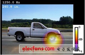
Acoustic image recognition of tires and exhaust noise at 50 km/h at 1,904.3 Hz
This article refers to the address: http://
“We chose a compact, DC-powered NI hardware that powers the microphones in the array.â€
- Samir N. Gerges, Federal University of Santa Catarina (UFSC)
challenge:
Develop a portable and affordable acoustic beamforming for noise source identification and noise source identification in other applications.
solution:
Use a spiral array of 32 microphones, NI LabVIEW software, NI Sound and Vibration Measurement Suite, and a 32-channel NI CompactDAQ system with eight NI 9234 4-channel Dynamic Signal Acquisition (DSA) modules to capture a visual image of the noise source. Thereby identifying the signals generated by the moving vehicle.
The Noise and Vibration Laboratory of the Federal University of Santa Catarina (UFSC) in Brazil conducts a variety of project research and participates in the research and development of the automotive industry to enable products to meet noise and vibration standards. In addition to supporting the development of the local industry, our school also promotes the academic development of undergraduate/postgraduate teaching and research.
The noise test is standardized to quantify the maximum incidental noise level during vehicle operation. In many countries, relevant government agencies have restrictions on sound testing, usually ISO362------ measuring the noise generated by road vehicle acceleration. These regulations are intended to record the level of major noise sources generated by normal vehicle travel in urban traffic, usually at a speed limit of 50 or 70 km/h. The vehicle can pass the noise test to verify that a car that meets the standards must not generate traffic noise that exceeds the specified limits.
Many parts of the car generate noise, including motors, exhausts, transmissions, and tires. The standard pass-through test does not identify the source noise that would cause the test to fail, so we need a technique that visualizes the sound field to distinguish between different sound sources. In this test, we used beamforming to see which sound sources significantly increase the overall noise and affect the vehicle's noise.
Beamforming
We built a beamformer, or "acoustic camera", which is constructed as a spiral array of 32 microphones with a maximum diameter of 1 meter between the microphones to capture the visual image of the noise source. We also built A metal grid of 1.1*1 meters. The positioning of the array is the same as the position of a single microphone in the standard test, the distance from the centerline of the channel is 7.5 meters, and the distance from the center to the ground is 1.3m, thus ensuring that all measurement conditions in the test pass are the same.
Our students built an array microphone using a low-cost electret microphone. Traditional directional array hardware consists of condenser microphones and preamplifiers on the market, but is too expensive for laboratory use. Creating a complete array of microphones saves money and provides students with valuable projects. NASA's Langley Research Center found that the microphone frequency response produced by the electret box is suitable for directional arrays where the amplitude and phase response of the audio spectrum is minimal and the high frequency changes are moderate. We completed the design based on the above research.
data collection
We use the NI USB-9162 high-speed C-series USB enclosure with eight NI 9234 DSA modules for data acquisition. We chose a compact, DC-powered NI hardware that powers the microphones in the array. The module's alias-free bandwidth is up to 20 kHz. In addition, the phase matching of the channel is quite important for acoustic beamforming, and the system specifies that the phase mismatch between any two channels cannot exceed one degree.
Since the system is DC powered, it is convenient to operate with a battery. Running LabVIEW software and sound and vibration measurement kits on your laptop makes it easy to convert voltage values ​​into engineering units used in noise measurements. In addition, the sound and vibration measurement kit complies with IEC61260 (electroacoustic, octave and fractional octave bandpass filters) and IEC61672 (electroacoustic and sound level meter) sound level measurement, weighting filter, octave analysis International standards, the measurement results are accurate and repeatable.
analysis
After the data acquisition is completed, we use a traditional delay addition beamforming algorithm to analyze it. We summarize the sound signals and describe the different propagation paths from the sound source to the different microphones. The sound source passes the acoustic camera at high speed (the speed of modern cars is still slow compared to the sampling speed of the data acquisition system), allowing the beam to concentrate and track the sound source through the microphone array. We must correct the Doppler effect of the inverse Doppler process, including amplitude and frequency corrections, to obtain a coherent sum of signals.
In order to calibrate the acoustic measurement data and the picture of the vehicle being tested, the amplitude of the superimposed noise, we started the buzzer (the main piece is about 90 decibels at 2.2 kHz) and the vehicle running at a constant speed of 50 km per hour, making it look like a regular Pass the array as you pass the test.
We have used this method instead of stable measurement because of its fast acquisition speed and high quality. It also presents the same type of recording through the measurement. The location of the buzzer allows for accurate alignment of photos and data.
Since the tires of the vehicle and the turbulent motion around the body generate noise during the movement, we apply this technique to the vehicle to accurately evaluate and identify the noise. Between this, we can very well reduce the noise passing through vehicles outside the wind tunnel.
At Christmas it is nice, in addition to the tree decorated with
large and colorful Christmas balls, to surround yourself with
decorations with Christmas motifs to be distributed around the house.
Create the right atmosphere with this led light garland.
Portable & Versatile
1.The item have a base and could stand on anywhere.
2.Integrated hanging hook holes for ease of display on wall or just rest on mantle, self, table or dresser.
3.Can be displayed standalone or combined with other pieces to create an eclectic lighting installation.
3.Create a whimsy showpiece on the cake or candy table during the Wedding.
Christmas Motif Lights,Led Motif Light,Christmas Motif Led Rope Light,Christmas Motif Light Decoration
XINGYONG XMAS OPTICAL (DONGGUAN ) CO., LTD , https://www.xingyongled.com