introduction:
This article refers to the address: http://
The electric vehicle instrument panel is a high-tech product that integrates LED , LCD display technology and stepper motor control technology to adapt to the development of electronic, digital and informational electric vehicles. It is a window for information exchange between drivers and cars. It is a multi-information display platform that displays motor status, battery pack status, driving information, chassis information, and alarms. Freescale 's S12HY32 is a 16 -bit MCU for car dashboard design. The author designed an electric vehicle dashboard with S12HY32 as the core. It uses stepper motor for pointer indication, has good data control characteristics, and can reflect the car in time. Various working conditions such as acceleration and deceleration, voltage and current rise and fall, improve the stability and positioning accuracy of the whole system, while retaining the advantages of intuitive, dynamic, and driver-friendly instructions. LED display of turn signal, far and near light conversion, door status, seat belt not prompted, charging indication, alarm and other status [ 1 ] , using LCD digital display odometer and fault status. This paper introduces the functional characteristics and application points of S12HY32 , and analyzes the design principle and hardware and software structure of electric vehicle dashboard.
1 hardware design
1.1 Introduction to MC9S12HY32
The MC9S12HY32 is a scalable entry-level automotive dashboard with a 16 -bit microcontroller that combines 16 -bit performance with many dedicated features [ 2 ] , such as LCD drivers and stepper motor drives, while serving CAN/LIN . The application is ideal for cost-effective automotive dashboard applications. Its chip resources and characteristics are as follows [ 3 ] :
1 , HCS12 CPU core with 32MHz bus frequency;
2 , 32KB program flash with ECC (error correction code) and 4KB data flash, 4KB on- chip SRAM ;
3 , field type LCD controller, can be configured up to 40x4 segments;
4 , 4 stepper motor controllers, can perform motor stall detection;
5 , two 16 -bit timer modules, can provide 16 -bit input capture, output comparison, counting and pulse accumulator function;
6 , 8 channel 10 -bit successive approximation ADC ;
7 , SPI / I2C module, an SCI module, supports LIN 2.0 , 2.1 and SAE J2602 communication;
8 , MSCAN module, support CAN protocol 2.0A/B .
1.2 system structure
The instrument panel consists of CAN bus interface, signal acquisition circuit, stepper motor, LCD , LED , and alarm device. It is used to collect and display vehicle operation information under various working conditions. Figure 1 shows the hardware structure of the instrument panel. The internal resources of S12HY32 introduce the hardware design of the instrument panel.
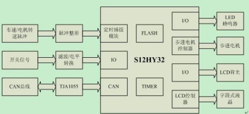
Figure 1 dashboard hardware structure
Figure 1 dashboard hardware structure
Picture 1: Dashboard hardware architecture
The S12HY32 internal resources are designed for instrumentation applications. The four stepper motor drivers provide pointer indications for vehicle speed, motor speed, current and battery pack voltage. The LCD controller can control field LCD display total mileage, subtotal mileage and motor faults. Information, internal MSCAN module supports CAN bus application, can obtain some key information through CAN bus, while retaining the ability to directly collect information: built-in timing capture module can capture and count vehicle speed / motor speed pulse, built-in ADC for motor temperature The acquisition of analog quantities. The following describes the circuit design of the instrument panel by taking the vehicle speed signal detection as an example.
1.3 vehicle speed signal detection
The speed of the vehicle is the key information that the instrument panel needs to display. According to the principle and topology of the vehicle, the source of the vehicle speed signal is the CAN bus or the vehicle speed sensor. The vehicle speed sensor outputs a pulse signal of 0-12V , and the signal frequency is linearly related to the magnitude of the vehicle speed, and increases with the increase of the vehicle speed [ 4 ] . The vehicle speed sensor signal is converted into a TTL level by the shaping circuit shown in FIG. 2 , and then The timing of the capture signal captures the rising or falling edge of the pulse signal, and statistical analysis can be performed to obtain the vehicle speed.

Figure 2 vehicle speed signal detection circuit
Figure 2 vehicle speed signal detection circuit
Picture 1:Speed ​​signal detection circuit
2 software design
2.1 software process design
Because the operating system is not used, the software design adopts the loop structure + interrupt software structure [ 5 ] , the main loop body completes the main function, and the interrupt service program performs the underlying protocol design and drive management. The software flow chart is shown in Figure 3. The following is a brief introduction. Let's take a look at the process. First, the global variables and the peripherals used (including IO , PWM , TIMER , SCI , CAN , LCD , MOTOR CONTROLLER ) are initialized. After the initialization is completed, the main loop is entered, and then the timer management and switching signal detection are sequentially performed in the loop body. Speed ​​detection, CAN communication management, mileage calculation and storage, alarm control, LCD control and stepper motor control. The order of each software module is shown in Figure 3. The following is a detailed description of the software design by taking the vehicle speed detection as an example.

Figure 3 software flow chart
Picture 3 Software Process
2.2 Vehicle speed signal detection software design
After the vehicle speed signal is shaped, the TTL pulse is obtained. The timing capture module of S12HY32 captures the edge change of the pulse in the interrupt mode [ 6 ] , and accumulates the number of pulses in the interrupt processing function. Design the pulse statistical structure and a 200ms cycle timer, using the "sliding time window pulse statistics method" to calculate the vehicle speed. The pulse statistical structure is designed as follows:
Typedef struct{
Uint8_t bank;
Uint16_t cnt;
}s_PulseCnt;
In the above structure, cnt represents the number of pulses, and bank indicates whether the data is valid. The sliding time window pulse statistics method is designed as follows:
Is defined as the number of pulses counted members of an array of structures Speed_pulse 6 [6], the vehicle speed pulse number stored periodically, the pulse rate is equivalent to the number of pulses in one second, there is the following formula:
Pulse frequency = (Speed_pulse[5].cnt-Speed_pulse[0].cnt) (2-1)
Vehicle speed = pulse frequency *FACTOR (2-2)
The FACTOR is determined by the gear ratio and the tire diameter.
The current calculated vehicle speed represents the average speed in the past 1 second. After the next 200ms arrives, the structural variables subscripted 1 to 5 are sequentially "sliding and copying" into the structural variables with subscripts 0 to 4 , and then updated. The structure variable subscripted as 5 , at which time the vehicle speed calculated according to Equation 2-1 and Equation 2-2 is an average speed between 0.2 and 1.2 seconds. The calculated speed of the vehicle in this way is more real-time, and the speed change is smoother. It is reflected in the change of the pointer, which is smoother and smoother, and can get a better visual experience. The code is as follows:
Void SpeedDetect(void)
{
Uint16_t i,j;
Uint16_t Carspeed_pulse_frequency=0;
If(1==Speed_detect_enable){
If(1==Timer[SPEED_PULSE_ACCUMU_200MS].overflow_flag){
For(i=0;i<=5;i++){
If(0==Speed_pulse[i].bank){
Speed_pulse[i].cnt=Car_speed_pulses;
Speed_pulse[i].bank=1;
If(5==i){
Carspeed_pulse_frequency=Speed_pulse[5].cnt-Speed_pulse[0].cnt;
Ev_speed=(float32_t)Carspeed_pulse_frequency*CAR_PULSE_FACTOR;
EvSpeedRangeCheck();
For(j=0;j<5;j++){
Speed_pulse[j].cnt=Speed_pulse[j+1].cnt;
}
Speed_pulse[i].bank=0;
}
Break;
}
}
}
}
}
Conclusion
The author uses the MC9S12HY32 design to realize an electric vehicle instrument panel. The hardware design of the instrument panel is described from the aspects of processor characteristics, hardware structure and vehicle speed signal detection. The instrument panel is described from the software flow design and the software implementation of the vehicle speed signal detection. Software design. The instrument panel has been tested by loading, stable operation and reliable function. It has entered the stage of small batch pre-production and has high practical value.
Lightsaber could be come true, this light stick design we make the light soft and nice. One way light saber or two ways light saber is available. The light sick could be install on floor and wall, indoor and outdoor are available. Different color could be provided. Just make the life more and more interested.
Fiber Optic Glow Stick Light,Fiber Optic Glow Sticks,White Fiber Optic Wands,Fiber Optic Sticks
ZHONGSHAN G-LIGHTS LIGHTING CO., LTD. , https://www.glightsled.com