The use of single-chip microcontrollers has become increasingly widespread. Many microcontrollers are equipped with a serial communication port, which significantly expands their application range. For instance, the serial port of the 51 series microcontroller is a full-duplex communication interface, allowing simultaneous transmission and reception of data. It can also support multiple communication modes, including multi-machine communication, by configuring the serial control register SCON. In real-world applications, long-distance multi-machine serial communication is often required.
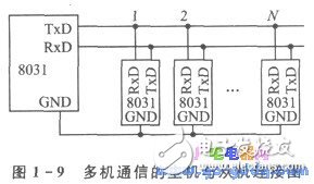
As commonly described, in multi-machine communication, the host and slave devices are connected as shown in Figure 1-9. The master device queries the slave, which responds through software programming. However, this method is typically limited to short distances—usually within a few meters. This is because the TTL-level signal from the serial port's TxD pin lacks sufficient driving capability and noise immunity for long-distance transmission. To achieve long-distance serial communication (ranging from tens of meters to several kilometers), an alternative solution must be adopted.
1. Long-Distance Serial Communication Circuit for Single-Chip Microcontrollers
To enable long-distance serial communication, differential drivers and receivers are added to the TxD and RxD signals of the microcontroller’s serial port. This allows for differential signal transmission and reception instead of single-ended level transmission. After adding the differential driver and receiver circuits, the multi-machine serial connection is shown in Figure 1-10. The empty squares represent the added differential components. As illustrated, after the addition, only the D+ and D− lines remain between the master and the slaves, eliminating the need for a common ground and reducing cable complexity. Notably, twisted-pair cables are used to further reduce electromagnetic interference. Importantly, the original communication program remains unaffected by these changes.

The circuit connects to the microcontroller via three signals: TxD, RxD, and GND. The output consists of two differential signals: D+ and D−. The circuit includes a 74LS04 NOT gate, an MC3487 differential driver, and an MC3486 differential receiver. Capacitors C1 and C2 filter high-frequency noise on the D+ and D− lines, while resistor Ri provides a pull-up for the D+ signal. The MC3487 and MC3486 are paired ICs that comply with the RS-422A standard, making them suitable for reliable serial communication. These components are widely available and relatively inexpensive, with domestic equivalents such as DS3487 and DS3486.
The pins of the MC3487 are shown in Figure 1-4, and its truth table is listed in Table 1-6. It is a four-channel RS-422A driver with three-state outputs. Pin 1 is the input for the first driver, while pins 2 and 3 are the non-inverting and inverting outputs, respectively. Pin 4 controls the output state: when it is low, the outputs go into a high-impedance state. The MC3486 is a quad differential line receiver with three-state outputs. Pins 1 and 2 are the inputs, and pin 3 is the output, which is controlled by pin 4. When pin 4 is high, the output is active.
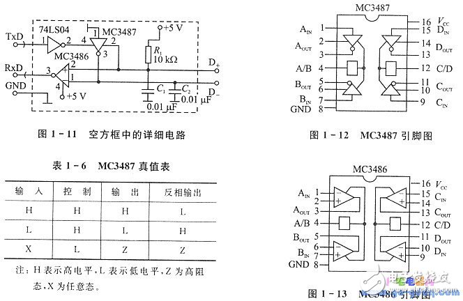
Let’s now analyze the operation of the differential driver and receiver circuit in Figure 1-11. Taking a serial transmission example, when TxD sends a low level, it is inverted by the 74LS04 and sent to the control pin 4 of the MC3487. At this point, the input pin 1 is grounded (low). According to Table 1-6, the output pins 2 and 3 will be low and high, respectively. These signals travel over the D+ and D− lines to the remote receiver. On the receiving end, the MC3486 receives a low level on D+ (pin 2) and a high level on D− (pin 1), resulting in a low output at pin 3. This matches the original TxD signal. When TxD sends a high level, the 74LS04 inverts it to low, placing the MC3487 outputs in a high-impedance state. At this point, the D+ line is pulled up via a resistor, resulting in a high level on D+ and a low level on D−. The receiving MC3486 then outputs a high level, matching the original TxD signal. This confirms that the received signal accurately reflects the transmitted one.
99% Ceramic Accessories,99 Porcelain Square Pieces,Ceramic Square Pieces,99 Ceramic Square Pieces
Yixing Guanming Special Ceramic Technology Co., Ltd , https://www.guanmingceramic.com