The basic function of the wireless charger is to transmit H power H to the battery in H wireless H mode through the coil. Simply charge the battery and receiving device on the charging platform. Experimental proof. Although the system can not be charged invisible. However, it has been possible to place multiple school appliances on the same charging platform while charging. Eliminate the trouble of wiring.
1 Wireless charger principle and structure
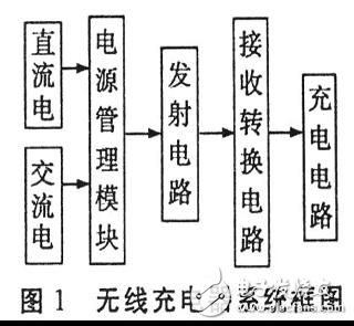
The wireless charging system mainly adopts the principle of electromagnetic induction, and energy transfer through the coil realizes energy transfer. As shown in Figure 1, when the system is working, the input terminal converts the AC mains into a DC power through the full-bridge rectifier circuit, or directly supplies the system with a 24V DC terminal. The DC power output after the H power management H module is converted into high frequency alternating current by the 2M active crystal oscillator to supply the primary winding. The energy is coupled through two H-inductor H coils, and the current output from the secondary coil is converted to direct current by the conversion circuit to charge the battery.
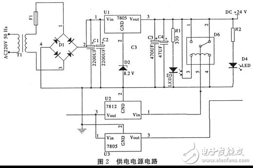
2 power management module
3 transmitting circuit module
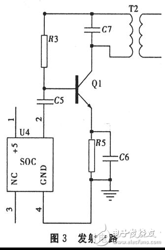
As shown in Figure 3, the main oscillator circuit uses a 2 MHz active crystal oscillator as the oscillator. The square wave of the output of the active crystal oscillator is filtered out by the second-order low-pass filter to obtain a stable sine wave output, which is output to the coil and the capacitor through a class C amplifier circuit composed of a triode 13003 and its peripheral circuits. The parallel resonant circuit radiates out. Provide energy to the receiving part.
4 receiving circuit module and charging circuit
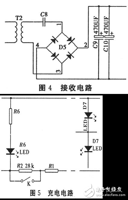
The wire diameter of the hollow core coupling coil of the parallel resonant circuit composed of the capacitance is measured as O. 5 mm, 7 cm in diameter, 47 uH in inductance and 2 MHz carrier frequency. According to the parallel resonance formula, the matching capacitance C is about 140 pF. thus. The transmitting portion uses a 2 MHz active crystal oscillator to generate an energy carrier frequency close to the resonant frequency.
Din Rail With Ups,New Design Din Rai ,35/15 Din Rai,Din Rai Switching Power
Wonke Electric CO.,Ltd. , https://www.wkdq-electric.com