Many friends actually made the results of the bile machine not ideal. There are two main reasons:
1. Since the knowledge of the electronic tube circuit and its application is the last century V. It was only available in the textbooks of the 1960s, and basically no tube knowledge was taught in the future. So the younger enthusiasts don't have a thorough understanding of tube knowledge.
2. Now many friends who make their own tube amplifiers are copied according to some reference circuits. They are not clear about many technical parameters in the reference circuit. They just follow the gourd painting scoop, and the finished product naturally designed in the heart It may not be able to achieve the desired effect. Based on my little knowledge and experience, I will discuss with you some problems in the design and production of amplifiers. If you do n’t like it, you can criticize and correct it. This article mainly discusses some problems in single-ended Class A small-power amplifiers, because Class A single-ended amplifiers are one of the best circuit forms for timbre and one of the more self-made circuit forms for enthusiasts.
1. Questions about output power 1. This type of single-ended tube amplifier generally uses a single power tube for amplification, which is limited by the maximum power dissipation of the power amplifier tube. The output power is generally not very large. Common circuits Medium output power is generally between 1W-15W. Table 1 is the output power and some common parameters of the Class A single-ended power amplifier circuit composed of some common power amplifier tubes.
The output power value in Table 1 has a great relationship with the working voltage of the screen electrode and the load impedance (primary impedance of the output transformer). Any change in data will cause a change in the output power value. The suitable occasion is related to the sensitivity of the speakers used. The higher the sensitivity, the larger the area of ​​use.
Tube type Filament voltage Filament current Maximum screen dissipated power Pin form Power transformer power Output power Suitable occasions
KT88,6550 6.3V / 1.6A 40W 8-pin tube socket 150W 15W 30 square meters or more
EL34,6CA7 6.3V / 1.5A 25W 8-pin tube socket 120W 11W 15-30 square meters room
6L6G, 6P3P 6.3V / 0.9A 19W 8-pin tube socket 100W 8.5W 15-30 square meters room
807, FU-7 6.3V / 0.9A 25W 5-pin tube socket 100W 10W 15-30 square meters room
6P14, EL84 6.3V / 0.76A 12W small 9-pin tube base 80W 5.4W Room under 15 square meters
6P15 6.3V / 0.76A 12W small 9-pin tube socket 80W 5W room under 15 square meters
6V6,6P6P 6.3V / 0.45A 12W 8-pin tube socket 70W 3.8W Room under 15 square meters
6P1 6.3V / 0.5A 12W small 9-pin tube socket 70W 5W room under 15 square meters
2. There are many different versions of the calculation method of output power. The calculation results of each version are basically the same, but the parameters required for the calculation are different. Now a simple calculation formula is provided for your reference: I2 × R / 2. Where I2 is the square of the quiescent current, R is the primary impedance of the output transformer, also known as the load impedance. After a lot of practice, the result of this formula is more accurate and practical.
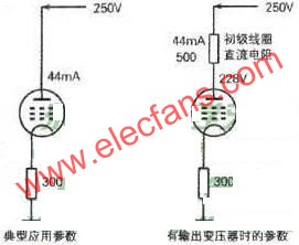
2. About the working voltage of the screen electrode In the tube manual, we can find the typical application parameters of the power amplifier tube. Generally, there is the parameter of the screen working voltage. For example, the screen voltage manual of the 6P1 tube is recommended to be 250V. There are many In the actual production, drawings and audiophiles choose the AC output voltage of the power transformer according to this parameter. In fact, this is not good, and the performance of the power amplifier tube is not well played, because the output transformer is connected in series in the screen-level circuit. . The primary coil of the output transformer has a DC resistance. When a quiescent current flows through the primary coil, a voltage drop will occur. At this time, the DC working voltage applied to the screen of the tube will be reduced. Other parameters will also change with the change of the screen voltage. Corresponding changes, I use the following Figure 1 and Table 2 to explain to you.
From Figure 1, we can see that after connecting the output transformer according to the operating voltage of the screen provided in the manual, the actual working voltage supplied to the tube screen of the tube is 22V lower than the typical operating voltage in the manual, and the entire power tube is reduced after 22V How have the other parameters changed? Please see Table 2 for comparison.
Table 2 Parameters in the manual Parameters with output transformer
Working voltage V 250 Working voltage V 228
Curtain voltage V 250 Curtain voltage V 228
Negative gate voltage V 12.5 Negative gate voltage V 11.4
Screen static current mA 44 Screen static current mA 38
Maximum screen current mA 88 Maximum screen current mA 76
Curtain current mA 7 Curtain current mA 6
Screen internal resistance KΩ 42.5 Screen internal resistance KΩ 44.5
Transconductance mA / V 4.9 Transconductance mA / V 4.67
Output power W 5 Output power W 3.97
You can see the changes in its data from Table 2. Because the frequency response requirements of the output transformer are now higher than the early requirements, the number of turns in the primary coil is also large, and the DC impedance is large. Therefore, we must consider the DC voltage drop generated by the primary coil of the output transformer when making the self-made tube amplifier, so as to achieve the application parameters provided in the manual.
3. The problem of output transformer The output transformer is the soul of the amplifier. If there is no output transformer, there will be no so-called gall odor. When the parameters of all components are unchanged, replace the output transformer of different manufacturers The replayed sound is also different. The design and manufacture of the output transformer during the self-made tube power amplifier determines the final result of replaying the sound. There are many versions of the design of the output transformer. The following two examples are given for your comparison (see Table 3 and Figure 2). Let us take the calculation of the inductance (L) as an example to explain.
The second calculation method formula remarks The second calculation method formula remarks
Primary coil inductance L unit (H) RL is the best load impedance of the tube (Ω) fL is the lowest playback frequency (Hz) Primary coil inductance L unit (H)
The minimum cross-sectional area of ​​the core S unit (cm2) Ip is the static DC current of the tube screen (mA), L is the primary inductance (H) The minimum cross-sectional area of ​​the core S unit (cm2) P is the rated power of the transformer
The number of turns of the primary inductance coil Np lave is the average magnetic field line length of the iron core, S is the cross-sectional area of ​​the iron core, L is the inductance The number of turns of the primary inductance coil Np u is the permeability of the iron core
Transformer coefficient (k) Ro is the secondary load impedance (Ω), n is the transformer efficiency at low power and is calculated at 75%, RL is the primary load impedance (Q) The correction factor K is greater than 1
The number of secondary coil turns Ns Ns = K × Np K is the transformation coefficient, Np is the number of primary inductance coil turns Ns R is the secondary impedance, n is the transformer efficiency
Air gap length G unit (mm) Ip is the static current of the tube screen (mA), Np is the number of primary inductor coil turns Air gap length G unit (mm) G = NpLo / 600 Io is the primary coil static current (mA)
The unit of primary and secondary coil diameter (mm) is calculated according to current density 3A / mm2 The unit of primary and secondary coil diameter (mm) is calculated according to current density 2.5A / mm2
Calculation of inductance A calculation method is:, where L is the inductance (unit H), RL is the best load impedance of the tube (unit Ω), and fL is the lowest playback frequency (unit Hz). Another calculation method is: where RL is the best load impedance of the tube (unit Ω) and fL is the lowest playback frequency (unit Hz). 3.14 is the constant when the lowest low frequency response is -1dB. The constant 0.159 in the first calculation method is based on the data when the lowest low-frequency response is -3dB, so the calculation formula should be selected according to your needs for the lowest low-frequency response. It can be seen from the above two calculation formulas that the final results of different versions of the calculation formulas are different.
Most of the output transformer design materials that we can see in various publications are many years ago, and some are still incomplete. The data of the output transformers are kept confidential by various manufacturers. This brings it to some friends who want to do it by themselves. There is a lot of trouble, so the success rate of self-made single-ended output transformers in amateur conditions is not high. Why can I make a high-quality output transformer under amateur conditions? The answer is yes. I provide some experience of making an output transformer for your reference. There is no detailed calculation formula. However, the performance of the output transformer produced in this way is already very good.
Determination of the lower limit of the lowest replay frequency:
The output power of Class A single-ended tube power amplifiers is not very large, and the selection of the lowest low-frequency lower limit frequency should be comprehensively considered according to the output power and the low-frequency lower limit of the connected speakers. Generally, when the output power is lower than 5W, the lower limit frequency is selected at 50Hz, when 5W ~ 10W, 30Hz is selected, and above 10W, the lower limit frequency is 20Hz.
Selection of primary inductance:
The primary inductance can be calculated according to the formula at -1dB.
Calculation of average magnetic circuit length:
It is very troublesome to calculate the average magnetic circuit length in the general formula, and now provides a simplest and accurate calculation formula, 5.57 × tongue width = average magnetic circuit length (EI core)
The above three data are important parameters to ensure the quality of the output transformer, no matter which design calculation formula you use should pay attention.
Selection of iron core under amateur conditions:
The EI type iron core is selected for the production of single-ended output transformers in accordance with the convention. However, there are many inconveniences in using the EI type iron core to make the output transformer under amateur conditions. The coils are not easy to be tightened, and the tension of the coils is not easy to maintain uniformity. After installing the iron core dipping paint, it is very troublesome to disassemble when adjusting the number of primary and secondary coils. Therefore, when I make output transformers in my spare time, I use R-type, C-type or ring-shaped iron cores. R-type and C-type iron cores can be used directly. The toroidal core is easy to get materials, and the price in the old electrical appliance market is very cheap. Many of the toroidal transformers produced in the early years were imported from Japan and rolled with 0.35 mm cold-rolled silicon steel tape. However, when using a ring-shaped iron core as a single-ended output transformer, an air gap must be left. My method is to use a EDM machine to cut a 0.1mm slit on the ring-shaped iron core as an air gap. In addition, pay attention to the selection of ring-shaped iron cores. Some iron cores are not completely wound with a silicon steel belt, and such iron cores cannot be used.
4. How to make an output transformer with a toroidal core 1. First, choose two toroidal transformers with the same performance. Since the power of toroidal transformers on the market is mostly above 50W, generally choose an iron core of 50 to 100W. After selecting, it is important to carefully check whether the iron core dipping paint is reliable. If it is not reliable, it can easily be deformed or scattered due to the tension during cutting. After confirming the firmness, use yellow sealing tape to wrap two or three layers on the iron core as if to wear enameled wire to ensure no deformation after cutting. At this time, the electric spark machine can be used to cut it. First cut a 0.1 mm slit to see if the iron core is deformed. If there is no deformation, pad the paper with yellow sealing tape and wind it tightly along the outer core of the iron core. If it is found that the core is deformed, cut another knife on the opposite side to divide the core into two. This is similar to the two halves of the C-type core. After a little polishing, a 0.1 mm piece of paper is placed on the pad. Can be put into use.
2. Determination of technical parameters:
Determination of output power: due to the large iron core (50-100W iron core), the power of the output transformer is determined to be 25W
Power frequency response range: set to (20Hz ~ 30kHz, -1dB), already able to meet the requirements of modern sound sources
Primary impedance setting: Since it is still a cumbersome thing to make an output transformer, the primary can be designed into a multi-tap form to meet the needs of different power amplifier tubes, respectively 500Q, 2700Q, 3500Q, 5000Q
Selection of primary wire diameter. Because the window is large enough, the wire diameter is slightly thicker as 0.23 mm (according to 2.5A / mm)
Selection of secondary wire diameter: select 1.08mm wire diameter (according to 2.5A / mm2)
After the above parameters are determined, the winding can be carried out. In the above parameters, I did not give the number of primary and secondary coils. This data is explained in the winding process. The tools and auxiliary materials for winding the transformer are not described in detail. know. But you must prepare an AC voltage regulator and a multimeter that can measure AC current. This is an important tool.
3. Winding method and process:
①First measure the length of a circle around the core, then measure the diameter of the inner circle of the ring core, and calculate the circumference of the inner circle. Divide the circumference by the wire diameter of the enameled wire used, you can know the approximate number of windings of the first layer, cut the wire to the threading shuttle according to the length of each circle, and wind a layer on the iron core radially, Do not overlap for counting. After winding, connect the AC voltage regulator and the multimeter AC current file, zero the output terminal of the voltage regulator, and then slowly adjust the output voltage upwards while energizing, and observe the change of the current. When the current reaches 10mA, stop the voltage regulation. Measure the output voltage of the voltage regulator and calculate the required number of turns per volt AC voltage. The audio voltage of the single-ended power amplifier of Class A generally does not exceed 250V. Use the known number of turns per volt × 250 = the total required lap number.
â‘¡Calculation basis and formula:
According to the primary inductance formula, the maximum load of the output transformer is 5000Ω, L = 5000 / (3.14 × 20) = 79.6 (H). When there is no special measuring instrument, it is not easy to measure the inductance at 20Hz, so only a simple but very reliable method, using 50Hz alternating current to qualitative measurement. Known voltage 250V, frequency 50Hz, quiescent current 10mA, seeking inductance and inductance.
Inductance × L = U / I = 250V / 10mA = 25000Ω, inductance H == 25000 / (6.28 × 50) = 79.6. This data is very close to the requirement of low frequency full power of the power amplifier. And this method does not need to calculate the core data and understand the quality of the core in advance, and can be measured at any time during production. Knowing the total number of turns at 5000Ω, you can use the transformer impedance formula to calculate the number of turns and secondary turns required for other primary impedances. The formula is as follows:
, Z1 is the maximum impedance, Z2 is the impedance at the tap, the total number of turns divided by the transformation ratio is equal to the number of turns at the tap.
For example, it is known that the maximum load impedance is 5000Ω, and the total number of turns is 4000 turns. To find the number of turns at the tap when the load impedance is 3500Ω, substitute the formula n == 1.195, the total number of turns ÷ transformation ratio = 4000 ÷ 1.195 = 3347 turns By analogy, the number of turns at any impedance tap can be calculated. This formula is also used for the secondary, but it is generally divided by the transformer efficiency coefficient to take 0.9.
The number of turns required at 8Ω. Substitute into the formula n == 25, 4000/25 / 0.9 = 178 turns, the secondary should be around 178 turns.
After winding a layer, all the data will come out. When winding, the secondary will be clamped in the primary, and the installation of dipping paint will not be described in detail. Finally, the AC voltage regulator and the multimeter AC current file are used to verify and measure it. The measured data is shown in Table 4. Such a self-made output transformer with excellent performance is successfully manufactured.
Table 4 Primary impedance Ω 20Hz, required inductance at -1dB L (H) 50Hz, required inductance at -1dB L (H) 50Hz AC voltage (V) to be applied during measurement Static current to be measured when qualified (mA) Inductance L (H) at 50Hz when qualified
5000 79.6 31.8 250 10 79.6
3500 55.7 22.2 250 14.2 55.7
2700 42.9 17 250 18.5 42.9
500 7.9 3.18 150 60 7.9
V. Problems with power supply The power supply of the tube amplifier is different from that of the ordinary transistor amplifier. The single-ended Class A tube amplifier has a static power consumption that accounts for more than half of the total power consumption after startup, while the ordinary transistor amplifier has less than the static power consumption after startup. The total power consumption is 10%, so the two are different.
Figure 2 is a typical low-power tube power supply circuit. From the figure, we can see that the high-voltage part is two sets of coils with center taps. Full-wave rectification is performed by a double vacuum rectifier diode 6Z4. CLC is composed of C1, L, and C2. The type circuit performs filtering. This circuit has two disadvantages: (1) The secondary high voltage requires two sets of coils. The two coils wound during self-made are not easy to be symmetrical, resulting in inconsistent output AC voltages of the two sets of coils. Due to the limitation of the core window, the wire diameter is generally thin, so the wire resistance is large, and the pressure drop after loading is also large. (2) Due to the limitation of the maximum screen current of the 6Z4 rectifier (300mA), the capacity of C1 cannot be too large, because when the capacity of the capacitor C1 is large, the instantaneous charging current of the capacitor at startup may exceed the maximum screen current of the 6Z4 rectifier. Cause damage to the rectifier 6Z4. Therefore, the filter capacitor capacity of this circuit is selected to be small, and the filtering effect is not ideal. Moreover, the filter inductance L is not easy to do well in amateur conditions.
Figure 3 shows a rectifier filter circuit. In this circuit, the transformer secondary high voltage has only one coil, so that the wire diameter can be thicker when the core window is equal, and it is much more convenient and simple when winding. The high voltage winding passes first Crystal diodes are used for bridge rectification, so that the capacity of capacitor C1 can be increased to hundreds or even thousands of uF. The DC filtered by C1 is then rectified again by 6Z4. The purpose of this is that the 6Z4 rectifier has a high-voltage delay It can prevent damage to the screen of the power amplifier tube and omit the high-voltage delay start circuit, and it has a more daring taste than rectification with crystal diodes. The capacity of capacitor C2 is generally selected below 200u F, because the filter capacitor in the entire circuit is sufficient And the secondary rectification is carried out. The ripple of the DC power output by this circuit is already very small, which creates conditions for ensuring a quiet background after the whole machine is installed. According to the different requirements of the power amplifier circuit for the current, the corresponding tube rectifier can be selected.
If there is no suitable power transformer in hand, some alternatives can be used to restructure. In amateur conditions, the old computer switching power supply can be used for restructuring. Generally, the power of the ATX power supply that is eliminated now is above 200W, and its output power can basically meet the requirements of various single-ended Class A tube amplifier dual-channel power amplifiers. The introduction is as follows: Figure 4 is a simplified diagram of a classic ATX power supply. From the figure, you can see that the core of the entire switching power supply is the control driver IC TL494 or KA7500B. Both of the above driver ICs have the function of adjustable output voltage. Take After arriving at this power supply, first connect three silicon diodes in the fan circuit to prevent damage to the fan when adjusting the output voltage. Then find the voltage divider resistor connected to the first pin of the IC, find the + 5V output sampling resistor, remove it, and replace it with an adjustable resistor with a larger resistance value. After powering on, slowly adjust the adjustable resistor to make the voltage at the + 5V terminal Just raise it to 6.3V. At this time, the resistance of the adjustable resistor is measured and re-welded with a fixed resistance, so that the original 5V output becomes 6.3V, which is used by all the tube filaments. After completing the above steps, remove the transformer and note the pins of each winding. Then disassemble the magnetic core, remove the original coil in turn and record the number of turns of each winding in detail. Because the original switching power supply magnetic core window is too small to put the high-voltage winding, you need to choose a larger magnetic core window. It is easy to find on the old color TV switching power supply board. It is not expensive to buy a new core and skeleton. Generally 2-3 yuan is enough.
The winding structure of the pulse transformer of the general ATX power supply is shown in Figure 5. In order to meet the needs of 5V / 22A current, the general 5V winding is used in parallel with three strands of 0.83mm enameled wire, and 12V / 8A is connected in series with the 5V winding in parallel with two wires. When we use it for the power supply of the tube amplifier, we don't need such a large current, so we need to reselect the wire diameter of the enameled wire when rewinding. The specific winding parameters are shown in the label in Figure 4. Put the top of the changed pulse transformer down and fix it with adhesive on the printed board, and then connect the primary coil, 5V and 12V coil to the original position on the printed board respectively. The 4 fast recovery diodes for high voltage use lap welding Method: Weld on the tap pin of the pulse transformer to select the required voltage end. Then power on and check the 5V terminal to see if it can output 6.3V DC voltage. If it can output 6.3V DC voltage, it means that the pulse transformer has been successfully reformed. If the voltage deviation is within 15%, the resistance of the sampling resistor can be readjusted to meet, if the deviation is too large The winding data of the pulse transformer should be checked, if not, the winding should be re-winded. Check the voltage of the cooling fan, increase or decrease the number of diodes connected in series in the fan power circuit according to the situation to ensure that the voltage is stable at 12V, so that the fan can work safely and steadily. This modified ATX power supply can be used for the power supply of the tube amplifier. Of course, the problem of using a switching power supply to supply power to the tube amplifier has been controversial in the circle. It depends on how the designer chooses. According to my personal use of these two power supplies, the switching power supply has no effect on the sound quality, and the filament supply is still very stable, will not be affected by changes in mains, and the weight is much lighter than the iron core transformer.
Sixth, the problem of matching with speakers The output power of Class A single-ended amplifiers is relatively small, and this factor should be taken into account when pairing with speakers. Most of the speakers currently produced have low sensitivity in order to reduce their own distortion. For Class A single-ended amplifiers, it is difficult to push them up. When paired with a Class A single-ended amplifier, it is best to choose some speakers with higher sensitivity. The level of sensitivity is not only related to the sensitivity of the speaker itself, but also closely related to the structure of the Speaker Box . Among the common speaker cabinet structure forms, the sensitivity from high to low is horn-type speaker, transmission line speaker, inverted speaker, and closed speaker. Horn speakers should be the first choice for Class A single-ended amplifiers. Because the speaker unit is unchanged, the sensitivity of the horn speaker is about 10dB higher than that of the Enclosed Speaker, which means that the sound pressure generated by this horn speaker when the input power is the same is greater than that of an enclosed box of the same volume 10 times, which is very beneficial to the playback of high-fidelity signals of Class A single-ended amplifiers. However, the production of horn-type speakers is more difficult, and the difficulty should be fully estimated when making homemade. The following gives a table of the relationship between the speaker sensitivity and the required input power for everyone to choose the speaker type reference.
In terms of speaker form, I personally think that it is better to choose a full-frequency unit structure, because the choice of a two-way or three-way structure can extend the high and low frequency power frequency response range, but after adding a crossover, it will increase the insertion. Loss increases the load on the Class A single-ended amplifier. In addition, the entire frequency response curve will be affected by the quality of the crossover. And the amplifier is limited by the frequency response curve of the output transformer power, and it is impossible to output audio power as low as a few Hz and as high as a few + KHz like a transistor amplifier. Therefore, it is not necessary to blindly pursue the ultra-wide frequency response speakers for the speakers matched with the Class A single-ended amplifiers. The frequency response range of the speakers should be selected according to the frequency response range of the output amplifier of the amplifier.
Headphone speaker is a king of speaker unit which is used for headphone, it also called headphone driver. These speakers have high sound pressure level, fast frequency response, wide frequency response range and low distortion. Headphone Speakers are mainly used for voice headphone (e.g. customer service phone, call center headphone, military intercom headset- ) and music headphone (e.g. Bluetooth headphone, sport headphone, game headphone-).
Our main headphone speakers include:
1) From the diameter, we have speakers in 23mm ~ 57mm.
2) From the impedance, we have speakers of 32ohm/150ohm/300ohm/1000ohm.


FAQ
Q1. What is the MOQ?
XDEC: 2000pcs for one model.
Q2. What is the delivery lead time?
XDEC: 15 days for normal orders, 10 days for urgent orders.
Q3. What are the payment methods?
XDEC: T/T, PayPal, Western Union, Money Gram.
Q4. Can you offer samples for testing?
XDEC: Yes, we offer free samples.
Q5. How soon can you send samples?
XDEC: We can send samples in 3-5 days.
Bluetooth Headphone Speaker,Sport Headphone Speaker,Hifi Headphone Speaker,Music Headphone Speaker
Shenzhen Xuanda Electronics Co., Ltd. , https://www.xdecspeaker.com