Traditional wired anti-theft alarms only sound the alarm locally when a burglary is detected. There is no controller inside, which is easy to be damaged and invalid, and installation and expansion are not convenient. The wireless anti-theft alarm designed in this paper is controlled by a single-chip computer, which is powerful and easy to expand into a multi-purpose smart home system.
System hardware circuit
1. Overall structure The overall structure of the intelligent alarm system hardware is shown in Figure 1, which mainly includes a central controller and a transceiver module. 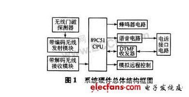
Use AT89C51 single chip microcomputer, the circuit is shown in Figure 2. P3.2 (INT0) is connected to the anti-theft detector, used to detect theft, if the theft occurs, trigger external interrupt 0. P2.1 connects to the voice circuit to realize voice playback control. P2.3 is connected to the telephone interface chip to realize analog off-hook control. P1.0 output simulates remote control. P1.4 connect the alarm buzzer. P0.0 ~ P0.3 are connected with D0 ~ D3 of MT8888 respectively, used as data bus. P2.0 is connected with RS0 of MT8888 to control the selection of MT8888 internal register. The CS of P2.7 and MT8888 controls the gating of MT8888. P3.3 (INT1) is connected to the 24 pins of the telephone interface chip and is used to detect ringing. P3.6 and P3.7 are connected with WR and RD of MT8888 respectively, and control the read and write operations of MT8888. 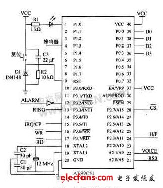
2. Detector and wireless transmitting and receiving circuit The detector uses wireless door magnet, which is composed of a permanent magnet and a door magnet main body (with a normally open reed switch inside). The wireless transmitting circuit is contained in the main body of the door sensor, and the receiving part is a super-regeneration module circuit. PT2262 / PT2272 form a coding and decoding chip pair. When the permanent magnet is away from the reed switch by a certain distance, the detector immediately emits a 315 MHz high-frequency radio signal containing the address code and its own identification code (data code). The receiving circuit determines whether it is the same by identifying the address code of this radio signal The alarm system, then according to its own identification code, determine which detector alarm.
3. DTMF transceiver circuit The alarm circuit shares a telephone line with the user's telephone. Choose MT8888 DTMF transceiver, combined with MCU and voice circuit, to realize the detection of various telephone signal tones, automatic dialing; or decode the remote telephone key signal and send it to MCU to realize remote control 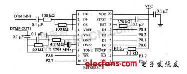
4. Voice circuit ISD1420 is selected as the basic recording and playback circuit, all address lines are set to 0, and the starting address of playback is 0. When you press and hold the S3 key, the recording starts and the data is stored from address 0 until the memory is full or the keys are released. When the S1 key is pressed, playback starts. 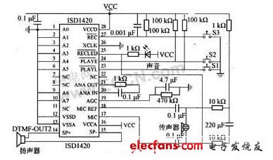
5. Telephone interface circuit 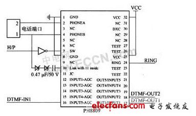
Both the DTMF transceiver circuit and the voice circuit need to be connected to the outside world through the telephone interface circuit, and the PH8809 telephone interface chip is selected.
system software
1. The main program flow system is controlled by a single chip microcomputer. When there is a theft, the buzzer circuit is activated, and a preset telephone alarm is automatically dialed; or remote control is accepted. 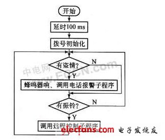
2. Telephone alarm process 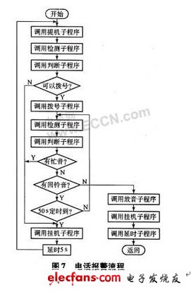
3. Remote control subroutine flow 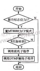
The intelligent anti-theft alarm system has complete functions, convenient installation and easy application. Replace other sensors, such as fire, temperature, smoke detectors, can be used as a fire alarm system. In addition, by expanding the external memory, the number of probe interfaces of the host, the display module, the voice circuit, etc., the system can be made more intelligent and more powerful.
No robbery occurred. When the head of the household called back, a ring was detected. When the number of rings was set and no one answered, the system automatically picked up the phone to connect the phone, waiting for the head of the household to enter the command through the telephone keypad, and the command through DTMF Transfer to the host computer, complete various remote control actions after decoding.
The detection subroutine is used to obtain the echo signal after pick-up, and get a count value. The judgment subroutine determines that the detected echo is dial tone, busy tone, and ring back tone according to the standard of the program-controlled switchboard. The dialing subprogram dials the preset phone call under dialing conditions. If the other party is busy or no one answers after ringing, it will delay for a while and wait for the next round of dialing. After the dialed call is connected, the playback subroutine will play back the pre-recorded alarm voice.
Carton size: 56*34*40cm
Filtration effect: above 95%
CE Certification
Suitable for respiratory protection, filtering dust, haze, bacteria, droplets and other harmful particles in the air.

Filters out more than 95% of air particles, keeping you away from pollutants and allergens, and is also perfect for pet allergens. Protective masks help prevent coughing and sneezing water from entering the nose and mouth. Three protective layers help you purify each breath and keep it sterile.
FAQ:
Advantages:
1. WE ARE FACTORY! We have our ownshare factory in shenzhen, Very welcome to visit if available.
2. OEM & ODM
3. Short delivery time
4. Environmentally-friendly material
5. Good workmanship
6. We always ship by international express, air and sea.
7. We serve with best quality and service.
Shenzhen Dianjiang Engineering Co. LTD , https://www.isourceled.com