Realization of ASI of DVB-C video transmission interface
In the transmission interface of the current DVB-C broadcast television system, there are two MPEG-2 video transmission interface standards: asynchronous serial interface standard ASI and synchronous parallel interface SPI. There are a total of 11 useful signals in SPI. Each signal is differentiated into two signals to improve the anti-interference of transmission. DB25 is used for transmission on the physical link. Therefore, the connection is more and complicated, the transmission distance is short, and it is prone to failure. However, SPI is a parallel 11-bit signal, which is easy to process and has strong extensibility. Therefore, the output of the current general MPEG-2 video encoder and the input of the video decoder are standard parallel 11-bit signals. ASI uses serial transmission, only one coaxial cable is needed for transmission. The connection is simple and the transmission distance is long. According to the advantages and disadvantages of SPI and ASI, the conversion between SPI and ASI of the transmission signal is required.
1 SPI signal structure
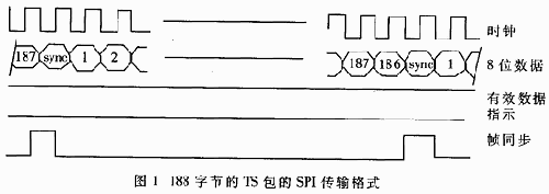
The parallel transmission system SPI includes a one-bit clock signal, 8-bit data signal, one-bit frame synchronization signal PSYNC and one-bit data valid signal DVALID. The frame synchronization signal corresponds to the sync byte 047H of the TS packet, and the DVALID signal is used to distinguish the length of the TS packet from 188 bytes or 204 bytes. When the TS packet length is 188 bytes, the DVALID signal is always high, and all signals are synchronized with the clock signal. The SPI data format is shown in the figure.

2 ASI interface
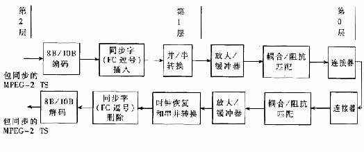
ASI transport streams can have different data rates, but the transmission rate is constant at 270Mbps, so ASI can send and receive MPEG-2 data at different rates. The ASI transmission system has a layered structure. The top layer and layer 2 use the MPEG-2 standard ISO / IEC 13818- (Systems), and layer 0 and layer 1 are FC fiber channels based on ISO / IEO CD 14165-1. FC supports a variety of physical transmission media. This solution uses coaxial cable transmission. Figure 2 is a block diagram of an ASI transmission system based on coaxial cable.

Figure 2 Block diagram of ASI transmission system based on coaxial cable
First convert the 8-bit codeword of the packet-synchronized MPEG-2 transport packet into a 10-bit codeword; then in parallel / serial conversion, when a new word is required and the data source is not ready, it should be inserted A K28.5 synchronization word to achieve ASI's fixed 270Mbps transmission rate. The formed serial bit stream will be sent to the coaxial cable connector through the buffer / drive circuit and the coupling network. There are three methods for inserting a synchronization codeword: a single byte of the transmission codestream cannot be a syncword before and after; a single byte of the transmission codestream must be a syncword; or a combination of both.
The received data that arrives at the coaxial cable must first be coupled to the circuit that recovers the clock and data through the connector and the coupling network, and then performs serial / parallel conversion; in order to recover byte synchronization, the ASI decoder must first search for K28.5 synchronization Word, once the synchronization word is searched, the boundary is demarcated for the data received subsequently, thereby establishing the correct byte arrangement of the output byte of the decoder; finally, 10 / 8-bit conversion is performed to restore the MPEG-2 packet synchronization TS stream data. But the K28.5 sync word is not valid data, so it must be deleted when decoding.
3 ASI interface implementation plan
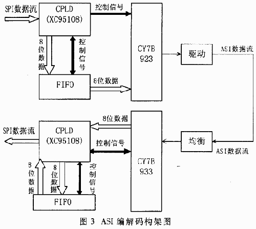
In this solution, the MPEG-2 TS code stream is provided by a single-chip MPEG-2 encoder MB86390, which outputs a parallel 11-bit signal that conforms to the SPI standard, and the TS packet length is 188 bytes. In the SPI / ASI conversion scheme, CYPRESS company cyb923 / cyb933 chip, asynchronous FIFO and logic programmer CPLD are mainly used.
cyb923 mainly realizes 8 / 10bit conversion of code words, inserts synchronization word K28.5 and parallel / serial conversion. The transmission rate of ASI is constant at 270MHz, and the input MPEG-2 TS code rate is different, so to use FIFO to achieve rate matching, you need to logically control the communication between the input SPI data, FIFO, and cyb923. Considering the comprehensive performance, price and program complexity, this solution uses the CPLD logic programmer XC95108 of xilinx company; use VHDL programming to realize their logic control. ASI decoding is also a similar process, cyb933 mainly implements 10 / 8bit conversion, removing the synchronization word K28.5 and serial-to-parallel conversion.
3.1 ASI code
In the encoding process of ASI, only the eight-bit data of MPEG-2 TS and one-bit TS code rate transmission clock are input to CPLD. Because in this scheme, the TS format is 188 bytes, so the data valid signal DVALID is always high, CPLD ignores this signal, just receives the TS stream data, and does not care about the synchronization header of the TS stream. The PSYNC frame synchronization signal is also ignored. The CPLD writes the received data to the FIFO at the TS code rate clock. When the FIFO is half full, the CPLD receives the half full signal of the FIFO, and then the CPLD sends a FIFO readable signal to the cyb923, and the cyb923 reads the data in the FIFO at 27Mbps; when the CPLD counts to cyb923, it reads a certain amount of FIFO data, CPLD Then send the FIFO unreadable signal to cyb923 to prevent the FIFO from reading empty. The parallel maximum speed of the MPEG-2 transmission code rate is 27/8 = 3.375Mbps, and the read FIFO rate is 27Mbps, so the FIFO will not overflow. Considering the delay, this solution uses a smaller capacity FIFO7202. Cyb923 fills the ASI code stream with K28.5 when the FIFO is unreadable to maintain a fixed transmission rate of 270Mbps. Finally, the serial data can be transmitted through the coaxial cable after being driven. In this solution, the insertion of the synchronization word K28.5 adopts the method of not all the K28.5 synchronization words before and after a single byte of the transmission code stream. Compared with the other two schemes, this scheme is relatively simple to judge and process.
3.2 ASI decoding
At the receiving end of ASI, the input ASI code stream is equalized and input to the cyb933 chip. It first locks the ASI code stream clock by the internal clock phase-locked loop, detects the synchronization word K28.5; after finding it, it determines the ASI bit stream sequence, and then performs serial / parallel conversion.
It can be seen that the detection of K28.5, that is, byte alignment is an important prerequisite for ASI decoding, so cyb933 defines a set of methods for detecting byte synchronization. Considering that transmission errors and other reasons may cause false K28.5, cyb933 uses a double-byte confirmation method. That is, two consecutive bytes are K28.5, only to confirm the byte synchronization, and then enter the normal single-byte decoding state. In the decoding state, if the CPLD counts that 16 of the 64 decoded bytes are incorrect, the CPLD must send a message to cyb933, requesting cyb933 to perform byte synchronization again.

After byte synchronization, because K28.5 is the synchronization byte inserted by cyb923 and cannot be output as valid data, cyb933 automatically skips these synchronization bytes. When cyb933 detects valid data, cyb933 will output an indication that the current data is valid. If you use this signal as a write valid FIFO, the data in the FIFO must be valid data. When the FIFO is half full, after CPLD receives the half full signal of the FIFO, the CPLD reads the data in the FIFO and determines the sync byte of the TS packet according to whether the read byte is 047H; if the sync word of the TS packet is found, The corresponding frame synchronization signal is restored. At this time, the CPLD counts 188 to restore the complete TS packet. If the next byte is not 047H, the input data is incorrect. CPLD will discard these data until the 047H synchronization word is found. During this period, CPLD outputs TS empty package. After re-packet synchronization, CPLD began to count and output the correct 188-byte MPEG-2 TS packet, thereby recovering the correct 11-bit signal of SPI. Similarly, when the FIFO data is unreadable, the CPLD also outputs TS empty packets to maintain the output MPEG-2 code rate constant.
In the design of SPI to ASI, the SPI data is directly ASI encoded without considering the error. The main consideration is that the SPI data is output directly from MB390 without being transmitted over a long distance, thus reducing the complexity of ASI encoding logic control. In the process of ASI decoding, ASI data is transmitted over a long distance, and the factors of bit errors must be considered, so the re-synchronization design of bytes and packets is added to increase the anti-interference ability. This scheme has realized the mutual conversion of SPI / ASI well in practical application.
DVB-T Technical Manual
The GFCI will not protect you from line contact hazards (i.e. a person holding two "hot" wires, a hot and a neutral wire in each hand, or contacting an overhead power line). However, it protects against the most common form of electrical shock hazard, the ground-fault. It also protects against fires, overheating, and destruction of wire insulation.
Ground Fault Circuit Interrupter UL
Ground Fault Circuit Interrupter UL,Auto-Monitoring Ground Fault Circuit Interrupters,Ground Fault Circuit Interrupter,Outlet Ground Fault Circuit Interrupter
Hoojet Electric Appliance Co.,Ltd , https://www.hoojetgfci.com