Guo Wangsu
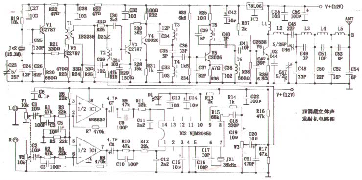
The 1W FM stereo transmitter circuit introduced in this article is composed of two parts: the audio modulation unit circuit and the modulated wave RF amplification unit circuit. The audio modulation unit circuit uses two ICs, and debugging becomes extremely simple. The main vibration stage of the modulated wave RF amplifier circuit adopts crystal frequency stabilization, and the phase modulation circuit is located after the local oscillator circuit, so the frequency stability of this machine is extremely high. The LC frequency-selective resonant circuit of the frequency doubling stage adopts a double-tuned frequency-selective circuit with a wide passband, a small rectangular coefficient, and good phase frequency specificity, which has a huge suppression effect on stray and useless harmonics other than the resonant frequency. The multi-segment band-pass and low-pass filters connected to the output end of the final power amplifier make the radio waves emitted by the wireless more pure and single, and even the TVs working close by will not be interfered. It is a high-performance transmitter circuit suitable for imitation of radio communication enthusiasts.
The circuit is shown in the figure. The dual preamplifier IC1 of the audio modulation circuit uses the high-quality, low-cost op amp NE5532. The NJM2035D is used as the IC signal synthesis circuit IC2 of Lixiu. High-fidelity audio signals from the Poker Dynamic Microphone or CD player are input from the L and R terminals, and the voltage amplitude of the input signal is controlled by the W1 and W2 coaxial potentiometers and then sent to IC1 for high-fidelity amplification. IC2 has â—‹ 1 foot and â—‹ 14 foot as the audio signal input terminal of Lixiu sound. After a series of processing of this IC internal function circuit, the synthesized Lixiu sound signal is output from â—‹ 9 pin. This signal is superimposed with the 19KHZ pilot signal output by the â—‹ 8 pin, and the appropriate signal component is selected by W3 and sent to the phase modulation of the radio frequency circuit.
The main vibration level of the transmitting circuit is composed of crystal V1, crystal JX2 and other components. Oscillation frequency FO = 15.3MHAZ. V2 is a buffer amplifier stage, the signal output by it is coupled to the phase modulation stage via T1, and is to be modulated by the audio signal. Varactor diode D2, inductance T2, resistors R24, R25, R26 form a bridge phase modulator. R24, R25 and R26 are the three bridge arms of the bridge phase modulator, and the fourth bridge arm is composed of T2 and D2. The audio modulation signal is added to the fourth bridge arm via C20 and R18. The frequency-modulated signal generated by phase modulation is sent to V3, V4 buffer and amplified by C30, and then a sine wave signal that is 3 times of FO is selected by the double-tuned frequency selection loop composed of T3, C34, C35, T4, C36, and C37, that is, FO × 3 = 15.3 × 3 = 45.9MHZ. V5 double-amplifies and amplifies this frequency signal, and selects the double-frequency signal (45.9 × 2 = 91.8MHZ) by the double-tuned frequency selection circuit consisting of T5, C39, C40, T6, C41, and C42, and sends it to V6 Power amplification. The RF amplified signal output by V6 is filtered by bandpass and low-pass (and impedance matching) filters composed of L2 ~ L5 and C45 ~ C54 to filter out unnecessary harmonic components and then sent to the antenna to radiate radio waves to the surrounding space.
At the time of production, the audio modulation unit circuit and the radio frequency unit circuit should be separately manufactured on two circuit boards. The radio frequency unit circuit should adopt overall shielding measures. W1 and W2 are coaxial volume potentiometers, and IC1 selects NE5532, a high-quality and low-cost, beautiful sound operational amplifier. IC2 selects NJM2035D. JX1 uses 38kHZ crystal. D1 uses ordinary light-emitting diodes. W3 is a 10K trimmer resistor. R1 ~ R18 use 1 / 16W five-color ring metal film resistor. C1 ~ C21 use high-quality capacitors. JX2 selects 15.3MHZ crystal. C23, C46, ​​C47 are 5 / 25PF high-frequency trimmer capacitors. V1, V2, V3 use 2SC2787, V4, V5 use 2SC2026. V6 selects 2SC2538, the tube parameters are: PCM = 3W, ICM = 0.4A, FT = 175MHZ. The varactor diode D2 uses IS2236. Except for C42 and C56, which are high-quality electrolytic capacitors, C23 ~ C56 are all high-frequency ceramic capacitors. R19 ~ R38 use 1 / 8W common carbon film resistor, R39 use 1W carbon film resistor. T1 ~ T6 are all wound on the 7 × 7 type high frequency middle circumference. The primary of T1 is Φ0.21mm high frequency enameled wire, which is wound 6 turns in the first to third slots, and the secondary is in the third slot. Wrap 3 turns; T2 uses Φ0.21mm high-frequency enameled wire in the first and second slots each 9 turns; T3, T4 uses Φ0.38mm high-frequency enameled wire in the first to third slots each 2 turns; T5 〠T6 uses Φ0.38mm high-frequency enameled wire in the 2nd to 3rd slots to wind 2 turns each. L1 ~ L5 are high-frequency enameled wire core inductors with a diameter of 3.5mm, which are all wound with Φ0.51mm high-frequency enameled wire. L1 is wound 5 turns, L2 is wound 4 turns, L3 is wound 5 turns, L4 is wound 3 turns, L5 Around 5 turns. IC3 selects LM78L067. The antenna adopts a double cross type omnidirectional antenna, which is mounted at a height of more than 10 meters from the ground and led to the radio frequency output end of the machine with a 75-5 high-quality coaxial cable.
When debugging the circuit, you should first connect a 75Ω high-frequency dummy load resistor at the RF output to prevent damage to the RF power tube V6 during no-load. The high-frequency voltmeter measures 2V high-frequency voltage at the collector of V2 to prove that V1 starts normally. When measuring the collector of V2 with the test rod of the frequency meter, adjust the fine-tuning capacitor C23 with a non-inductive small screwdriver to make the frequency meter display the value as "15.300MHZ" completed the debugging of the local oscillator and buffer amplifier stage. The high-frequency voltmeter measures 5V high-frequency voltage at the collector of V4, which proves that the buffer amplifier stage of V3 and V4 works normally. Adjust the magnetic cores of T3 and T4 so that the high-frequency voltmeter measured on the base of V5 shows that the value of the high-rate meter is "45.900MHZ" and the debugging of the triple frequency circuit is completed. When the magnetic cores of T5 and T6 are adjusted to make the base of V6, the frequency meter displays the value of "91.800MHZ" and the debugging of the double frequency circuit is completed. When marking the high-frequency voltage at point A in the high-frequency voltmeter measurement chart, adjust the trimmer capacitors C46 and C47 to make the high-frequency voltage at point A ≥ 12V. When marking the high-frequency voltage at point B in the high-frequency voltmeter measurement chart, use a non-inductive flat screwdriver to turn the turns of L3, L4, L5 to make the high-frequency voltage at point B ≥ 10V. When the dummy load is sensed at a distance of 10 ~ 20cm, the frequency meter shows that the value is "91.800MHZ" and the initial adjustment of the bandpass and lowpass filters composed of L3 ~ L5 and C49 ~ C54 is completed.
When the dummy load was removed and the antenna was connected for the actual emission experiment, the author found that its output power was smaller than that when the dummy load was connected. The main performance is that the high-frequency voltage at point B in the figure is much lower, indicating that the antenna impedance at this time is less than 75Ω. Use a non-inductive flat small screwdriver to turn the turns of L3, L4 and L5 respectively, so that the high-frequency voltage measured at point B ≥ 10V completes the formal debugging of the wiper amplifier output circuit composed of V6, L2 ~ L5 and other components.
The debugging of the audio modulation unit circuit needs to be carried out in coordination with the FM stereo radio receiver Yang. The L and R ends are fed into the high-fidelity audio source signal output by the CD player, and then the handheld FM stereo radio is pulled away to listen to a certain distance. When the amplitude of the signal input to the L and R terminals is too strong, the sound signal heard in the receiver is turbid noise. At this time, the W1 and W2 knobs are turned counterclockwise until the sound signal heard by the receiver is clearly distinguishable from the right until. If it is heard that the restored sound signal has clipped distortion, the FM deviation modulation potentiometer W3 until the sound signal transmitted from the receiver is realistically reproduced.
After the above debugging, you can hold the FM stereo radio to test the transmission distance. When receiving with an ordinary FM stereo radio with a receiving sensitivity of 500μV, the open distance is about 1.5km and the non-open distance is about 500m, and the FM stereo indicator lights normally. When receiving with an advanced FM stereo radio with a receiving sensitivity of 0.5μV, the open distance exceeds 5km, and the stereo indicator still glows normally.

Follow WeChat

Download Audiophile APP

Follow the audiophile class
related suggestion
â—† Overview of circuits Many homes now have TV sets, VCDs, video recorders ...
![[Photo] Homemade TV station](http://i.bosscdn.com/blog/20/06/41/719137229.gif)
Sudden power failure at night will cause inconvenience to your life. The emergency light circuit in this article is simple and the cost is low.
![[Photo] Self-made simple emergency light](http://i.bosscdn.com/blog/20/07/11/2621141295356.jpg)
The feature of the remote control switch is that no special remote control mobile phone is needed, and the ready-made color at home can be used ...
& n ...
![[Photo] High-frequency signal probe of self-made multimeter](http://i.bosscdn.com/blog/20/06/41/523012544.jpg)
BA1404 is enough for general FM transmission, but it has a fatal flaw: ...
![[Photo] Homemade small power amplifier and speaker (TDA1521)](http://i.bosscdn.com/blog/20/06/41/5131037985.jpg)
'+ data.data.username +' '; dom + ='
The ear-hook earphone refers to a kind of earphone that is added with an ear-hook on the side of the earphone for convenient use. Different from in-ear earphones, ear-hook earphones are a type of earphones and earbuds that are divided according to how they are worn. Design principle: the connection between the two units of the earphone and the wearing of the fixed beam can be canceled, with a beautiful hook to make it hang on the ear.
Advantages:
1: The way of ear hooks ensures the reliability of the user's wearing. In the design of earplugs, the unit is often enlarged to meet the needs of sound quality.
2: The design of the earhook fully demonstrates the design capabilities of the earphone manufacturer, from the design to the reliability of the wearing of the ergonomic design.

Earhook Earphones,Ear Hook Headphones,Earhook Headphones With Mic,Ear Hook Headphones With Mic
Shenzhen Linx Technology Co., Ltd. , https://www.linxheadphone.com