1. The background and significance of the installation of the device in the high-voltage power grid
In recent phases, some substations of Hebei Power Grid have adopted a "hand in hand" structure, which cannot fully realize the true dual power supply. When the system fails, it often causes 220kV and 110kV substations to lose voltage, resulting in load loss, which greatly affects The power supply reliability in some areas of our province, but due to the limitation of power grid development funds, it is impossible to fundamentally solve the problem by improving the power grid structure in a short period of time. In this case, the problem needs to be solved, and only by installing safety automatic Device to remedy, that is, the remote remote automatic projection device based on optical fiber communication .
2. Comparison of several communication methods
2.1, TCP / IP Ethernet
The remote self-launching solution of Ethernet communication is the application of computer network communication technology, and the data communication between devices is completed by establishing the TCP / IP protocol in Ethernet, so as to realize the mutual communication between the self-investment in the local area network. Each station's backup automatic investment device needs to install sending and receiving terminals, each with its own IP address. The characteristics of this method are: you must establish a local area network between substations, you also need to design and develop a dedicated self-transmitting transmission and reception terminal, an Ethernet server; communication is vulnerable to interference, communication exchange information takes too long, poor security performance, maintenance Difficult.
2.2, GPRS technology
The characteristic of GPRS technology is the wireless IP connection between point-to-point or center-to-multipoint and multipoint, the data is communicated through GPRS channel in the form of "code", and it is used to transmit operating status information, fault information and trip command information . This method is characterized by wide coverage, fast transmission speed, and long-term online operation. The disadvantages are: poor security performance, uncontrollable real-time information exchange, poor security performance, and large investment in equipment.
2.3 Optical fiber communication
At present, optical fiber communication is basically implemented between each 110kV substation. Its optical fiber communication transmits operating status information, fault information and trip command information. It has no errors, fast transmission speed, large transmission capacity, simple and flexible interface, and convenient conversion. It is basically free from external electromagnetic interference and other advantages, and is the most reliable communication method. On this basis, any communication needs of remote self-launching devices can be realized.
This kind of scheme has small investment, quick effect, safe and accurate, and basically no interference, so it is currently the best communication scheme to achieve remote self-investment.
3. Software function design for self-investment
3.1 Analysis of operation mode
In response to the problem in FIG. 1, the positions of the four switches in two adjacent substations controlled by the installed device are shown in FIG. 2.
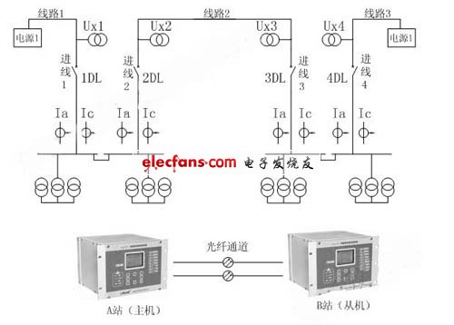
Figure 2. Device installation diagram
As shown in Figure 2, according to the power system operation rules, at least one of the four circuit breakers is in the open state, and the operation mode with operational value is analyzed, as listed below:
Method 1: 1DL, 3DL, and 4DL are closed, and 2DL is open.
Method 2: 1DL, 2DL and 4DL are closed, and 3DL is open.
Method 3: 2DL, 3DL and 4DL are closed and 1DL is open.
Method 4: 1DL, 2DL, 3DL are closed, and 4DL is open.
Method 5: 1DL and 4DL are closed, and 2DL and 3DL are open.
According to the requirements of power consumption, the most ideal mode of operation is mode five, there is no loss of contact lines, but when the system is operating in mode five, line 3 is not live, and the equipment of line 3, including cables and poles, is easy to be stolen. Energized equipment will aging; in addition, if it is prepared for automatic operation, the line charging time is also very long, and the time for power supply switching is also longer, so it is generally not considered. Select mode 1 and mode 2 during normal operation. Power supply 1 supplies power to station A, and power supply 2 supplies power to station B. If power supply 1 or power supply 2 fails, the power will automatically turn to mode 3 or mode 4.
In mode 3 or mode 4, the power supply is borne by power supply one or power supply two, which does not meet the requirements of the power system and can only be used as a temporary power supply mode.
The unique acicular radiator,360 degree dissipation small wind resistance. High heat dissipation efficiency ensuring that the LED chip can work for 50000 hours.
Color temperature 3000-6000K
Light≥90LM/W
Matching the 2.3.4 lane,tunnel and Landscape Lamp,floodlight dedicated lens.Ensure that intensity and uniformity.
Glare index Signification reduce the original LED Module size,removal of power supply problems.Low demands for application situation and installation personnel More suitable for the transformation of traditional lamps.

Technical parameters
Power :30W,30W,15W,15W
Structure size: 135×100×40 mm, 208×74×49 mm, 125×58×30mm, 380×40×25mm
Lens size: 135×100 mm, 186×64 mm, 125×58mm, 355×40mm
Input voltage: 220 V, 220 V ,220 V, 220 V
Input current: 0.132 A, 0.132 A ,0.123 A, 0.125 A
Luminous flux: 2760 LM ,2400 LM ,1230 LM ,1300 LM
Light effect: 92 LM/W 80 LM/W 82 LM/W 86 LM/W
Color temperature: 5000 K 5000 K 5000 K 5000 K
Power factor: 0.99 PF 0.98 PF 0.98 PF 0.99 PF
Working temperature: -40+50°C, -40+50°C, -40+50°C ,-40+50°C
Led Module,Led Modules For Signs,Led Module Bulb,Led Modules For Signage
Jiangsu chengxu Electric Group Co., Ltd , https://www.satislighting.com