Car instrumentation is an information exchange interface between driver and car, which plays an important role in car safety and economic driving. In recent years, with the development of automotive electronic technology, the display information of automobile meters has also been increasing, and the traditional mechanical pointer type automobile combination meter can not meet the current needs.
In particular, computers, microelectronics, and various fieldbus communication technologies are widely used. Intelligent digital instruments with embedded microprocessors as the core will be an inevitable trend in the development of automotive instruments. This paper gives a design scheme of embedded automotive digital instrument.
2 Hardware design
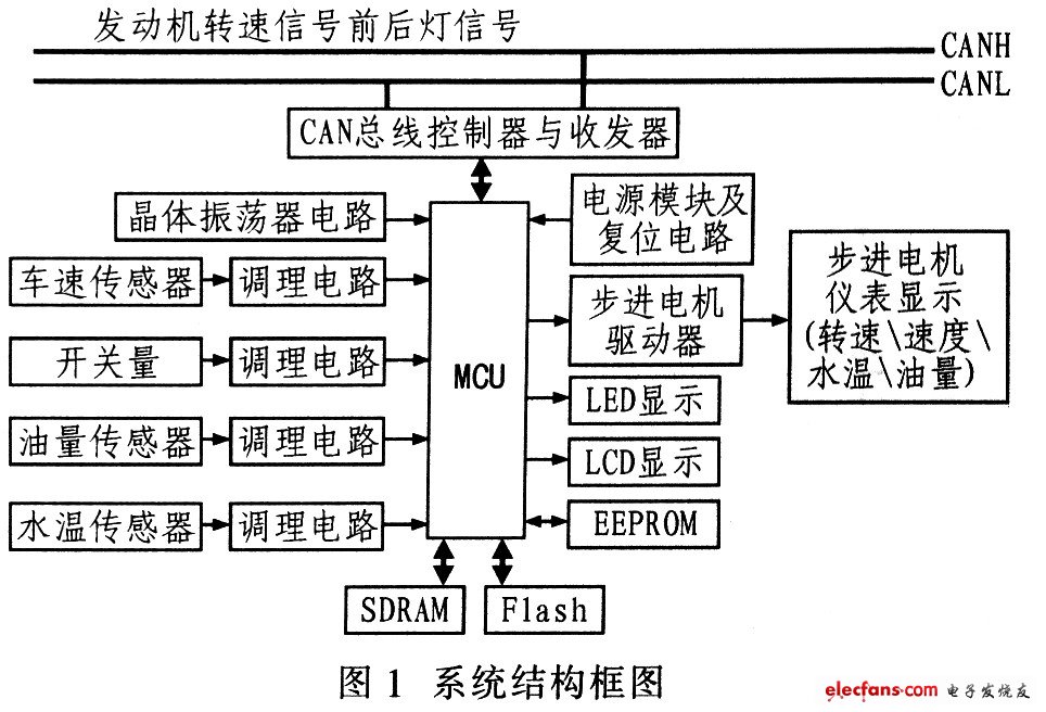
The signals that automobile instruments need to process are: vehicle speed, engine speed, water temperature, oil quantity, and various switching or alarm signals. Among them, the engine speed signal and the front and rear light signals are obtained from the CAN bus (engine electronic control module and front and rear light electronic control module), while the vehicle speed signal, water temperature, fuel quantity and other switching signals are obtained from the corresponding sensors.
The structure of the automobile digital instrument system is shown in Figure 1. This system uses a step meter to display the speed, engine speed, water temperature and fuel information, the mileage information is displayed by LCD, the switch or alarm signal is displayed by LED, and the serial port EEPROM is used for Store mileage information. The controller MCP2510 with Microchip SPI interface and the transceiver 80C250 form a CAN node, which is used to communicate with other CAN nodes in the car.
2.1 MCU, external expansion memory and mileage storage circuit
The system uses Samsung's ARM7TDMI device S3C44BOX as the main controller. S3C44BOX is a 16 / 32-bit RISC processor, its working frequency can reach 75 MHz, and its internal resources are rich. Because there is no memory inside S3C44BOX (internal SRAM is used for buffering), it is necessary to use bus expansion external memory, including program memory and data memory, using 16 Mbit: FlashSST39VF160 and 64 Mbit SDRAM HY57V641620 as program memory and data memory, respectively. The system also uses an AT24C04 storage device to store mileage information. AT24C04 is a 4 Kbit serial memory, which uses I2C bus to store mileage information.
2. 2 power and reset circuit
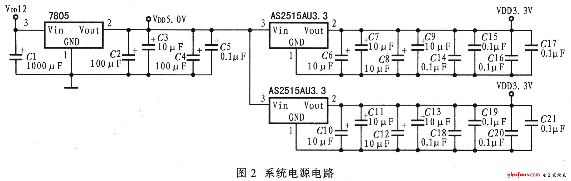
The automotive digital instrument system is powered by a car battery. The voltage of the car battery is about 12 V, and the system needs to use 5 V, 2.5 V and 3.3 V operating voltage. The S3C44BOX core operating voltage is 2.5 V, I The operating voltage of the / O port is 3.3 V, and 5 V operating voltage is required for the conditioning circuit and some driving devices. Therefore, the system selects the 7805 voltage regulator as the 5 V voltage converter, and AS2515AU2.5 and AS2515AU3.3 as the 2.5 V and 3.3 V voltage converters, respectively. The mileage information can be stored in time when power is off, and a 1 000 μF capacitor needs to be connected to the power ground. When the power is off, the large capacitor can ensure that the S3C44BOX works for a period of time and complete the storage of mileage information. The reset circuit uses a dedicated reset circuit IPM811 to achieve stable system startup. Figure 2 shows the system power supply circuit.
Corn Sheller,Hand Corn Sheller,Corn Sheller Machine,Hand Crank Corn Sheller
Hunan Furui Mechanical and Electrical Equipment Manufacturing Co., Ltd. , https://www.thresher.nl