Tags: POE IEEE
This article refers to the address: http://
Power over Ethernet (POE) overview
POE (Power Over Ethernet) refers to some IP-based terminals (such as IP phones, WLAN access points APs, networks) without any changes to the existing Ethernet Cat.5 cabling infrastructure. Cameras, etc., while transmitting data signals, can also provide DC power supply technology for such devices. POE technology can ensure the normal operation of existing networks while minimizing costs while ensuring the security of existing structured cabling.
POE is also known as POL (Power over LAN) or Active Ethernet, and is sometimes referred to as Power over Ethernet. This is the simultaneous transmission of data using existing standard Ethernet transmission cables. The latest standard specification for electrical power and maintains compatibility with existing Ethernet systems and users. The IEEE 802.3af standard is a new standard based on the Power over Ethernet (PoE) system. It adds the standard for direct power supply through the network cable based on IEEE 802.3. It is an extension of the existing Ethernet standard and the first international standard for power distribution. standard.
The IEEE began to develop the standard in 1999. The first vendors to participate were 3Com, Intel, PowerDsine, Nortel, Mitel and National Semiconductor. However, the shortcomings of this standard have always restricted the expansion of the market. Until June 2003, the IEEE approved the 802.3af standard, which specifies power detection and control issues in remote systems and provides access to IP phones, security systems, and wireless LANs over Ethernet cables to routers, switches, and hubs. The way in which devices such as points are powered is specified. The development of IEEE 802.3af includes the efforts of many corporate experts, which also allows the standard to be tested in all aspects.
A typical Power over Ethernet system is shown in Figure 1. Keep the Ethernet switch device in the wiring closet and power the twisted pair cable of the LAN with a power supply hub (Midspan HUB). At the end of the twisted pair, the power source is used to drive phones, wireless access points, cameras, and other devices. To avoid power outages, a UPS can be used.
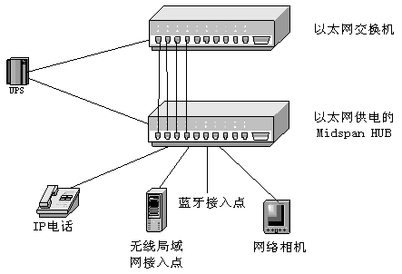
Figure 1 A typical Power over Ethernet system
Key technologies of POE
POE system configuration and power supply characteristics
A complete POE system includes two parts: power supply equipment (PSE, Power Sourcing Equipment) and power supply equipment (PD, Power Device). The PSE device is a device that powers Ethernet client devices and is the administrator of the entire POE Power over Ethernet process. The PD device is a PSE load that accepts power, that is, a client device of the POE system, such as an IP phone, a network security camera, an AP, and a PDA or a mobile phone charger, etc. (actually, any power Devices up to 13W can receive the corresponding power from the RJ45 socket. Based on the IEEE 802.3af standard, the two establish information about the connection status, device type, and power consumption level of the PD of the powered device, and use this as the power supply to the PD through the Ethernet.
The main power supply parameters of the POE standard power supply system are:
â—† The voltage is between 44 and 57V, and the typical value is 48V.
â—† The maximum allowable current is 550mA and the maximum starting current is 500mA.
â—† Typical operating current is 10 ~ 350mA, overload detection current is 350 ~ 500mA.
â—† Under no-load conditions, the maximum required current is 5mA.
â—† Provide three levels of electric power request for the PD device from 3.84 to 12.95W, up to 13W.
POE power supply process
When a PSE power supply device is placed in a network, the POE Ethernet power supply operation process is as follows.
â—† Detection: At the beginning, the PSE device outputs a small voltage on the port until it detects that the cable terminal is connected to a powered device that supports the IEEE 802.3af standard.
â—† PD end device classification: After detecting the power receiving device PD, the PSE device may classify the PD device and evaluate the power loss required by the PD device.
◆ Start power supply: During the start-up period of a configurable time (generally less than 15μs), the PSE device starts to supply power from the low voltage to the PD device until 48V DC power is supplied.
â—†Power supply: Provides stable and reliable 48V DC power for PD equipment, which can meet the power consumption of PD equipment not exceeding 15.4W.
â—† Power off: If the PD device is disconnected from the network, the PSE will stop powering the PD device quickly (usually within 300 to 400 ms) and repeat the detection process to detect whether the terminal of the cable is connected to the PD device.
When connecting any network device to the PSE, the PSE must first detect whether the device is a PD or not to ensure that no current is supplied to the Ethernet device that does not comply with the POE standard, as this may cause damage. This inspection is accomplished by providing the cable with a small current-limited voltage to check that the distal end has the required characteristic resistance. The full 48V is only supplied when the resistor is detected, but the current is still limited to prevent the terminal from being in an erroneous state. As an extension of the discovery process, the PD can also classify the power supply methods that require the PSE to help the PSE provide power in an efficient manner. Once the PSE starts to supply power, it continuously monitors the PD current input. When the PD current consumption drops below the minimum value, such as when the device is unplugged or when the PD device consumes power overload, short circuit, or exceeds the PSE power supply load, etc., the PSE will Disconnect power and start the test again.
The power supply device can also be provided with a system management capability, such as the application of Simple Network Management Protocol (SNMP). This feature provides features such as night shutdown and remote reboot.
Studying the power supply mode of the POE can be seen that there are two key issues to be considered in the power supply process, one is the identification of the PD device, and the other is the capacity of the UPS in the system.
Principle of POE power supply through cable
The standard Category 5 cable has four pairs of twisted pairs, but only two of them are used in l0M BASE-T and 100M BASE-T. IEEE 80 2.3af allows two uses as shown in Figure 2 and Figure 3.

Figure 2 is powered by the idle pin
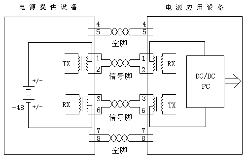
Figure 3 is powered by the data pin
When the idle pin is used for power supply, the 4 and 5 pin connections are positive, and the 7 and 8 pin connections are negative.
When the application data pin is powered, the DC power is applied to the midpoint of the transmission transformer without affecting the data transmission. In this manner, the pair 1, 2 and the pair 3, 6 can be of any polarity.
The standard does not allow the application of both cases. The power supply device PSE can only provide one usage, but the power application device PD must be able to adapt to both situations at the same time. This standard specifies that the power supply is usually 48V, 13W. It is easier for PD devices to provide 48V to low voltage conversion, but at the same time there should be a 1500V insulation safety voltage.
The POE standard also specifies an unshielded twisted pair cable, ie Category 3, 5, 5e or 6 cable, that should be used to transmit electrical power. It is clear that the existing cable installations that work with them do not require any changes, including Category 3, 5, 5e or 6 cables, various short wiring and patch panels, power outlet leads and connected hardware. The POE standard is compatible with the IEEE 802.3 standard series.
POE two power supply methods
The POE standard defines two methods for transporting DC power to a POE-compatible device using an Ethernet transmission cable: a method called Mid-Span that uses unused line pairs that are not used in the Ethernet cable. To transmit DC power, the corresponding Endpoint PSE supports POE-enabled Ethernet switches, routers, hubs, or other network switching devices. Another method is "End-Span", which transmits DC power simultaneously on the core line used to transmit data, and its transmission uses a different frequency than the Ethernet data signal. The Midspan PSE is a dedicated power management device that is usually placed with the switch. It has two RJ45 jacks for each port, one connected to the switch with a short wire and the other connected to the remote device. It is foreseeable that End-Span will be quickly promoted because Ethernet data and transmission use a common line pair, thus eliminating the need for dedicated lines for independent power transmission, which is only for 8-core cables and matching standard RJ. The -45 socket is of great significance.
Figure 4 is an example of a POE power supply system consisting of a power supply device PSE, a powered device PD, and associated equipment and an Ethernet transmission cable.
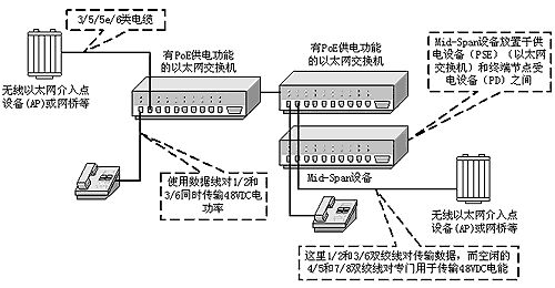
Figure 4 Example of a Power over Ethernet system conforming to the IEEE 802.3af standard
When the PD device is compatible with the POE standard, it can be powered directly from the Ethernet cable through the RJ-45 socket. For devices that are not compatible with the POE, the DC converter or the tap divider can be used to convert the voltage into POE-compatible. Voltage. These devices, sometimes referred to as active Ethernet splitters, take the DC voltage of the Ethernet cable and use it through a conventional DC outlet for the PD device.
Advantages of POE technology and expanded applications
The advantages of using an Ethernet cable for power supply are obvious:
â—† POE only needs to install and support a cable, which is simple and space-saving, and the device can be moved at will.
â—†Save costs. Many powered devices, such as video surveillance cameras, need to be installed where AC power is difficult to deploy. POE eliminates the need for expensive power and time to install power, saving money and time.
â—† Like data transfer, POE can supervise and control the device by using Simple Network Management Protocol (SNMP).
â—† The POE power supply device only supplies power to the equipment that needs to be powered. Only when the equipment that needs to be powered is connected, the Ethernet cable will have voltage, thus eliminating the risk of leakage on the line.
â—† A single UPS can provide power to all related equipment during power outage.
â—† Users can automatically and securely mix legacy devices and POE devices on the network, which can coexist with existing Ethernet cables.
â—† Make network devices easy to manage. Because the remote device can be remotely controlled, reconfigured, or reset when it is connected to the network.
â—† In wireless LAN, POE can simplify RF test tasks, and access points can be easily moved and accessed.
With the establishment of the IEEE 802.3af standard, a large number of other applications will also emerge quickly, including Bluetooth access points, lighting work, network printers, IP phones, Web cameras, wireless bridges, building security systems such as access control cards. Machine and monitoring system, etc. By merging new power supply devices on current Ethernet devices, users can provide 48V DC power on existing network lines, reducing the total cost of network construction and protecting investment. Manufacturers have already placed products on the market, such as the Midspan Hub with power.
Conclusion
Ethernet Power over Ethernet (POE) is a revolutionary technology that extends the power of Ethernet with a reliable DC power supply from the same Category 5/Cat5 twisted pair cable that currently carries Ethernet data. . POE will change the way network devices are powered, and network administrators can make the most of existing network infrastructure and deploy a whole new range of applications.
The road lamp lighting is a main light source configuration is most widely used in Road Lighting engineering,mainly is suitable for the city roads,lans wide road lighting and decoration,is the way the functional lighting products. Our company's road lighting products include Lotus Combination Lamp,High-low arm High-power LED lamps,Lift type High-mast lamp,Integrated Solar road light.
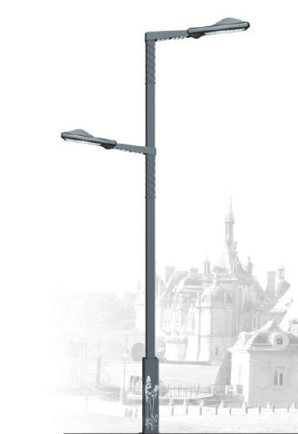

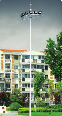

The main road generally use high-quality steel manufacturing,stable structure and generous,illumination power and the main rod highly visible road width of scientific allocation.To ensure that the surface brightness,no glare,uniform illumination.Long distance continuous configuration,can describe the spatial light continuous beauty,make city roads at night more grandeur.
Road Lighting Series,Road Lighting,Road Lighting Decoration,Road Lighting Book
Jiangsu chengxu Electric Group Co., Ltd , https://www.satislighting.com