I. INTRODUCTION
The rapid advancement of modern industry has significantly driven the development of automation technology and equipment innovation. Today, DCS (Distributed Control Systems), IPC (Industrial Personal Computers), PLCs (Programmable Logic Controllers), and smart meters are widely used in on-site production control systems, evolving into a distributed industrial automatic control system that integrates across the entire production process. In such systems, field communication technology plays a critical role. However, at the beginning, there was no unified communication protocol standard, leading to isolated communication protocols among different manufacturers. This resulted in incompatible communication networks, making it difficult or even impossible to connect devices from different vendors, which limited the flexibility of distributed control systems.
To adapt to market demands, some companies have released their communication standards for free. Over time, protocols like Modbus, developed by Modicon, have become widely adopted due to their compatibility and ease of use, becoming an industry standard. This paper presents the design of a distributed control system for a chemical fiber project, focusing on the implementation of a communication network based on the Modbus protocol.
II. SYSTEM COMPOSITION
1. System Structure
The system is composed as shown in Figure 1, which omits the acquisition and control of field instrument signals. The system host computer uses Yokogawa's CS3000 DCS system for centralized monitoring of the entire production process. The lower-level machine uses Omron's CS1H series PLC, located in three electrical control rooms. These PLCs manage field motors, OCV valves, flow switches, frequency converters, and perform execution, detection, start/stop control, feedback signal acquisition, and fault detection.
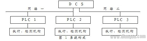 Based on real-time communication requirements, the DCS and three PLC control stations are divided into two independent communication networks: PLC1 and PLC2 with DCS one port form Network 1, while PLC3 and DCS two ports form Network 2. Due to differences in communication protocols between upper and lower machines, direct communication was challenging. To address this, the Modbus communication protocol was selected to establish the communication network for the distributed control system.
2. Communication Network Composition
2.1 Communication Protocol
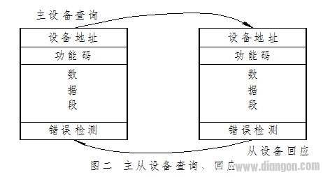
Modbus is a master-slave serial communication protocol suitable for industrial control. It uses inquiry-based communication to exchange information between master and slave devices, supporting device addresses from 1 to 247. It includes broadcast query and single-device query methods. Broadcast queries do not require device responses, while single-device queries follow a master-slave communication process, as shown in Figure 2.
Based on real-time communication requirements, the DCS and three PLC control stations are divided into two independent communication networks: PLC1 and PLC2 with DCS one port form Network 1, while PLC3 and DCS two ports form Network 2. Due to differences in communication protocols between upper and lower machines, direct communication was challenging. To address this, the Modbus communication protocol was selected to establish the communication network for the distributed control system.
2. Communication Network Composition
2.1 Communication Protocol
Modbus is a master-slave serial communication protocol suitable for industrial control. It uses inquiry-based communication to exchange information between master and slave devices, supporting device addresses from 1 to 247. It includes broadcast query and single-device query methods. Broadcast queries do not require device responses, while single-device queries follow a master-slave communication process, as shown in Figure 2.
 Modbus supports two transmission modes: ASCII and RTU. RTU mode is more efficient, allowing more data to be transmitted at the same baud rate, making it commonly used in industrial networks. The RTU message format is shown in Figure 3.
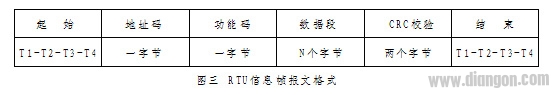 RTU mode does not include start and stop bits but uses a minimum of 3.5 character intervals as message boundaries. All characters in an information frame are hexadecimal digits (0–9, A–F). This system uses the RTU mode for single-device inquiry. According to the system configuration, DCS port 1 is set to addresses 01H and 02H for two PLC slave stations, while port 2 is set to 01H for one PLC. Read and write operations use function codes 03H and 06H respectively.
2.2 Network Composition and Hardware Introduction
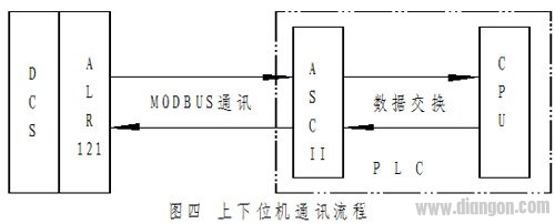
The network uses RS485 serial interface. Communication is achieved through 4-core shielded cables connecting the master and slave devices. The transmission distance can reach up to 1.5 km, full-duplex, with a baud rate of 19200, 8 data bits, even parity, and 1 stop bit. The DCS communication part uses Yokogawa's ALR121 communication module, equipped with Modbus communication software. The module can handle up to 4000 words of data. The PLC communication part uses Omron’s C200H-ASCII 21 programmable special unit module (ASCII module), which supports BASIC programming, has 200K bytes of program storage, and provides RS232 and RS485 serial ports. Through programming, various communications with peripheral devices can be achieved. The system converts DCS read/write commands and data via the ASCII module, enabling real-time data exchange with the PLC CPU unit, as shown in Figure 4.
RTU mode does not include start and stop bits but uses a minimum of 3.5 character intervals as message boundaries. All characters in an information frame are hexadecimal digits (0–9, A–F). This system uses the RTU mode for single-device inquiry. According to the system configuration, DCS port 1 is set to addresses 01H and 02H for two PLC slave stations, while port 2 is set to 01H for one PLC. Read and write operations use function codes 03H and 06H respectively.
2.2 Network Composition and Hardware Introduction
The network uses RS485 serial interface. Communication is achieved through 4-core shielded cables connecting the master and slave devices. The transmission distance can reach up to 1.5 km, full-duplex, with a baud rate of 19200, 8 data bits, even parity, and 1 stop bit. The DCS communication part uses Yokogawa's ALR121 communication module, equipped with Modbus communication software. The module can handle up to 4000 words of data. The PLC communication part uses Omron’s C200H-ASCII 21 programmable special unit module (ASCII module), which supports BASIC programming, has 200K bytes of program storage, and provides RS232 and RS485 serial ports. Through programming, various communications with peripheral devices can be achieved. The system converts DCS read/write commands and data via the ASCII module, enabling real-time data exchange with the PLC CPU unit, as shown in Figure 4.
 III. SOFTWARE IMPLEMENTATION
1. Address Allocation and Correspondence Table
The DCS human-machine interface (HMI) monitors field instruments using graphical symbols. The DCS I/O physical addresses correspond to the field signal acquisition. The DCS monitors field electrical actuators and detection mechanisms by matching DCS communication I/O addresses with PLC I/O physical addresses. Before programming, an allocation and correspondence table between DCS communication I/O and PLC I/O addresses must be established. Due to the complexity of PLC logic control, a direct association between PLC I/O physical addresses and DCS communication I/O addresses is inconvenient, so an indirect addressing method is used. The PLC's DM area is used as the indirect address area, connected to the DCS communication I/O area, and then linked to the PLC I/O area. For example, if DCW’s %WB000101 bit corresponds to D0000.00 bit, and D0000.00 connects to the PLC’s I0000.00 physical input point, the status of the field actuator can be fed back to the HMI. An upper and lower machine address allocation and correspondence table is established accordingly. Due to space constraints, the table is omitted.
2. Programming the ASCII Module
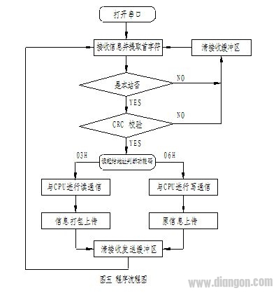
The ASCII module supports BASIC language programming and includes system instructions such as receive/send buffer operations, error control (CRC, LRC checks), and data exchange with the CPU unit. Programming is done using HyperTerminal software on Windows. By connecting the PC's serial port to the ASCII module's RS232 port, the module can be programmed, uploaded, downloaded, and debugged. Programs can also be written in WordPad and saved as text files, then downloaded to the ASCII module via HyperTerminal. The main workflow of the communication program is shown in Figure 5.
III. SOFTWARE IMPLEMENTATION
1. Address Allocation and Correspondence Table
The DCS human-machine interface (HMI) monitors field instruments using graphical symbols. The DCS I/O physical addresses correspond to the field signal acquisition. The DCS monitors field electrical actuators and detection mechanisms by matching DCS communication I/O addresses with PLC I/O physical addresses. Before programming, an allocation and correspondence table between DCS communication I/O and PLC I/O addresses must be established. Due to the complexity of PLC logic control, a direct association between PLC I/O physical addresses and DCS communication I/O addresses is inconvenient, so an indirect addressing method is used. The PLC's DM area is used as the indirect address area, connected to the DCS communication I/O area, and then linked to the PLC I/O area. For example, if DCW’s %WB000101 bit corresponds to D0000.00 bit, and D0000.00 connects to the PLC’s I0000.00 physical input point, the status of the field actuator can be fed back to the HMI. An upper and lower machine address allocation and correspondence table is established accordingly. Due to space constraints, the table is omitted.
2. Programming the ASCII Module
The ASCII module supports BASIC language programming and includes system instructions such as receive/send buffer operations, error control (CRC, LRC checks), and data exchange with the CPU unit. Programming is done using HyperTerminal software on Windows. By connecting the PC's serial port to the ASCII module's RS232 port, the module can be programmed, uploaded, downloaded, and debugged. Programs can also be written in WordPad and saved as text files, then downloaded to the ASCII module via HyperTerminal. The main workflow of the communication program is shown in Figure 5.
 Some sample code includes:
```basic
OPTION BASE 0
DIM R(128), FC(128)
R(48)=0: R(49)=1: R(50)=2: R(51)=3: R(52)=4: R(53)=5: R(54)=6: R(55)=7: R(56)=8
R(57)=9: R(65)=&h0a: R(66)=&h0b: R(67)=&h0c: R(68)=&h0d: R(69)=&h0e: R(70)=&h0f
R(97)=&h0a: R(98)=&h0b: R(99)=&h0c: R(100)=&h0d: R(101)=&h0e: R(102)=&h0f
OPEN #2, "COMU:19200,8,E,1"
A% = LOC(2)
IF A% = 8 THEN
REX$ = INPUT$(A%, #2)
...
ENDIF
GOSUB *ZFCL
IF ST = 1 THEN *JAOY ELSE *BACK
*JAOY
GOSUB *CRC
IF R = CRC THEN *WORK ELSE *BACK
...
```
Since the ASCII module uses ASCII, and RTU is a binary-based hex communication method, a code conversion program is included in the code.
CH5$ = MID$(REX$, 5, 1): CH6$ = MID$(REX$, 6, 1)
VOL = ASC(CH5$) * 256 + ASC(CH6$)
VOL$ = HEX$(VOL)
3. Program Optimization and Security Measures
In the data exchange between the ASCII module and the CPU unit, the ASCII module actively sends read/write requests, and the CPU executes the data exchange program upon receiving the request. This reduces the PLC scanning cycle and improves real-time communication performance.
In error control, the CRC-16 algorithm is used, achieving an error rate below 10^-14. If the information fails verification, the buffer is cleared and the DCS message is retransmitted.
For manual control, on-site buttons can be disabled on the HMI, and all operations are performed via the DCS. To ensure normal operation during severe network failures, a communication status timing detection procedure is added. If no signal is detected within 10 seconds, the PLC automatically enables on-site manual devices, and the DCS triggers alarms until the network recovers.
IV. CONCLUSION
Current distributed control system communication networks, including equipment, software, and overall architecture, are mostly produced by professional manufacturers, offering good performance. However, they still face challenges such as limited system configuration, narrow network structure, and high costs. This paper adopts the mature Modbus protocol, selects a programmable PLC module, designs an autonomous communication program based on the Modbus protocol, and constructs a communication network for the automatic control system. The network is easy to expand and maintain, featuring a simple structure, flexible application, convenient programming, and low cost. The system was successfully implemented in a chemical fiber production line, demonstrating stable and reliable performance, meeting the design requirements. So far, the system has been applied in several engineering projects, operating normally and delivering significant economic benefits.
The innovation of this paper lies in adopting the widely used Modbus communication protocol in the industrial field, utilizing the programmable PLC special function module, and designing a communication program that solves the system's communication architecture issue at a low cost, providing a flexible and compatible design idea for distributed control systems.
Some sample code includes:
```basic
OPTION BASE 0
DIM R(128), FC(128)
R(48)=0: R(49)=1: R(50)=2: R(51)=3: R(52)=4: R(53)=5: R(54)=6: R(55)=7: R(56)=8
R(57)=9: R(65)=&h0a: R(66)=&h0b: R(67)=&h0c: R(68)=&h0d: R(69)=&h0e: R(70)=&h0f
R(97)=&h0a: R(98)=&h0b: R(99)=&h0c: R(100)=&h0d: R(101)=&h0e: R(102)=&h0f
OPEN #2, "COMU:19200,8,E,1"
A% = LOC(2)
IF A% = 8 THEN
REX$ = INPUT$(A%, #2)
...
ENDIF
GOSUB *ZFCL
IF ST = 1 THEN *JAOY ELSE *BACK
*JAOY
GOSUB *CRC
IF R = CRC THEN *WORK ELSE *BACK
...
```
Since the ASCII module uses ASCII, and RTU is a binary-based hex communication method, a code conversion program is included in the code.
CH5$ = MID$(REX$, 5, 1): CH6$ = MID$(REX$, 6, 1)
VOL = ASC(CH5$) * 256 + ASC(CH6$)
VOL$ = HEX$(VOL)
3. Program Optimization and Security Measures
In the data exchange between the ASCII module and the CPU unit, the ASCII module actively sends read/write requests, and the CPU executes the data exchange program upon receiving the request. This reduces the PLC scanning cycle and improves real-time communication performance.
In error control, the CRC-16 algorithm is used, achieving an error rate below 10^-14. If the information fails verification, the buffer is cleared and the DCS message is retransmitted.
For manual control, on-site buttons can be disabled on the HMI, and all operations are performed via the DCS. To ensure normal operation during severe network failures, a communication status timing detection procedure is added. If no signal is detected within 10 seconds, the PLC automatically enables on-site manual devices, and the DCS triggers alarms until the network recovers.
IV. CONCLUSION
Current distributed control system communication networks, including equipment, software, and overall architecture, are mostly produced by professional manufacturers, offering good performance. However, they still face challenges such as limited system configuration, narrow network structure, and high costs. This paper adopts the mature Modbus protocol, selects a programmable PLC module, designs an autonomous communication program based on the Modbus protocol, and constructs a communication network for the automatic control system. The network is easy to expand and maintain, featuring a simple structure, flexible application, convenient programming, and low cost. The system was successfully implemented in a chemical fiber production line, demonstrating stable and reliable performance, meeting the design requirements. So far, the system has been applied in several engineering projects, operating normally and delivering significant economic benefits.
The innovation of this paper lies in adopting the widely used Modbus communication protocol in the industrial field, utilizing the programmable PLC special function module, and designing a communication program that solves the system's communication architecture issue at a low cost, providing a flexible and compatible design idea for distributed control systems.
A longpass (LP) Filter is an optical interference or coloured glass filter that attenuates shorter wavelengths and transmits (passes) longer wavelengths over the active range of the target spectrum (ultraviolet, visible, or infrared). Longpass filters, which can have a very sharp slope (referred to as edge filters), are described by the cut-on wavelength at 50 percent of peak transmission. In fluorescence microscopy, longpass filters are frequently utilized in dichroic mirrors and barrier (emission) filters. Use of the older term 'low pass' to describe longpass filters has become uncommon; filters are usually described in terms of wavelength rather than frequency, and a "low pass filter", without qualification, would be understood to be an electronic filter
Longpass Filters,Long Pass Filter,Longpass Filter,Long Pass Filters
Changchun Realpoo Photoelectric Co., Ltd. , https://www.optics-realpoo.com