(1) When removing a specific circuit board from the entire CNC machine, it is important to document its exact position and the corresponding cable numbers. Before and after disassembling fixed boards, make sure to remove the crimping parts and screws, and keep them in a designated box to prevent loss. After reassembly, all items from the box should be used; otherwise, the installation may be incomplete. (2) Always place the soldering iron in front of your hand, keeping it away from the circuit board being worked on. Trim the tip of the soldering iron appropriately to suit the size of the integrated circuits and avoid damaging other components during the soldering process. (3) When measuring resistance between lines, ensure that the power is turned off. To get an accurate reading, swap the red and black test leads twice and use the average as the reference value. (4) Most circuit boards are coated with a solder mask. Therefore, identify the solder joints as testing points without removing the solder film. Some boards have an insulating layer, so only the blade should be used to gently scrape the solder joint for insulation purposes. (5) Avoid cutting the printed circuits arbitrarily. Although some technicians are accustomed to checking for breaks, most CNC circuit boards feature double-sided or multi-layered holes with fine and dense traces. Once cut, it can be difficult to repair, and adjacent lines may be damaged. If a line needs to be cut, ensure you cut multiple lines at once to avoid misalignment. (6) Do not replace components randomly. Some technicians may replace parts without confirming the fault, leading to a higher false positive rate and potential damage to more expensive components. (7) When removing components, use a soldering iron and desoldering pump. Avoid pulling components forcefully. Do not heat the same pad repeatedly for long periods, as this can damage the pad. (8) When replacing new devices, ensure the pins are properly treated and avoid using acidic solder, which can cause corrosion or damage over time. (9) Document the positions of switches and jumpers. Never change their positions unless necessary. When performing multi-pole comparisons or swapping components, mark each component clearly to avoid confusion. This helps prevent good boards from failing due to incorrect connections. (10) Check the power supply configuration and type of the circuit board. Provide the required power supply separately if needed. Be cautious of high voltage, as some boards are directly connected to high voltage or include high-voltage generators. Proper insulation and caution are essential during these operations.

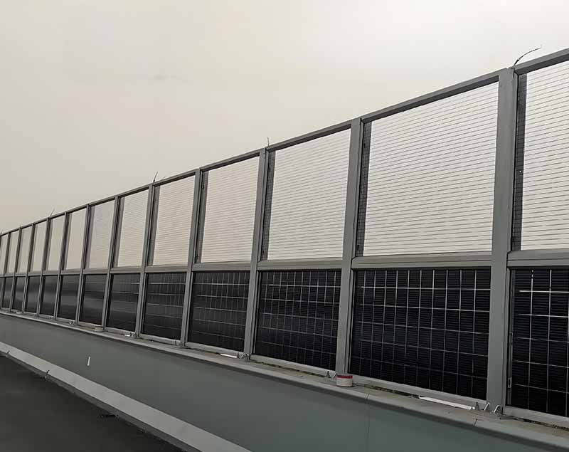
Photovoltaic sound barrier,Solar-powered sound barrier,Photovoltaic noise barrier,Solar noise barrier
Hebei Shuobiao New Energy Technology Co., Ltd. , https://www.pvbracketsystem.com