Wavelength division multiplexers and demultiplexers are a major component of almost all WDM systems and networks. Traditionally, multiplexers/demultiplexers (de/mux) are static devices that vary slightly in wavelength range as temperature changes. Almost as soon as the first static multiplexer/demultiplexer is commercially available, one dreams of a multiplexer/demultiplexer that enables a fast-tuned version of the wavelength. The fast-adjustable multiplexer/demultiplexer can be widely used in various fields, including fast code hopping technology in time/wavelength two-dimensional optical code division multiple access (OCDMA) systems. Improved QoS performance and enhanced security [1].
There has been little new development in previous tunable multiplexers. Recently, a 1xN MEMS-driven Gires-Tournois Interferometer (GTI) was used to make a fast-tuning multiplexer/demultiplexer [2]. The GTI uses a programmable micromirror array to replace the back reflecTIon plane in a conventional GTI structure. Functionally, this GTI actually acts like a tunable arrayed waveguide grating (AWG). The role [3], the output ports are all cyclically related to the relevant wavelength. For example, for a demultiplexer that includes N ports, the first wavelength is output from port 1, the Nth wavelength is output from port N, and the N+1th wavelength is output from port 1. After tuning, the N-1th wavelength can be output from port N, and the Nth wavelength can be output by port 1, and the N+1th wavelength is output by port 2. In our prototype device, the crosstalk between adjacent ports is 8 dB, while the MEMS mirror is tuned to 10 μs. Although basic device measurement papers have been published [2], system-level research has not yet been reported.
In this paper, we will demonstrate the system-level performance and fast conversion capability of a GTI-based 1x3 wavelength multiplexer/demultiplexer with a GTI with a tunable center wavelength. The GTI group delay ripple (GDR) measurement found that its GDR was below 5 ps. The 10Gb/s data transmission demonstration of this multiplexer/demultiplexer was found to have a power loss of less than 0.5 dB.
In addition, due to the periodic frequency shift phenomenon of the asynchronous optical orthogonal code in the 2D OCDMA system, the orthogonal code phenomenon is also caused [4]. Therefore, using this tunable multiplexer to implement Code Hopping is a simple and easy way. Since the eavesdropper needs to find the order of the code hopping while listening to the code itself, this increases the difficulty of eavesdropping, and thus the system security is greatly improved. At the same time, since the tunable encoder/decoder can allow a user to jump to a new code in the case where the other user's MAI (Multiple Access Interference) is reduced, the code hopping technique is also Proven to maintain the quality of service (QoS). The MEMS GTI can be used to perform code hopping while significantly improving performance (such as speed and simplicity) over other potentially competing technologies such as temperature tuned FBG or delay line switches. Below we introduce the code hopping test of the 2D OCDMA system using GTI.
Use GTI as a high speed switch
The output port of each multiplexer exhibits a periodic filter spectrum. By changing the voltage applied to the electrostatic MEMS actuator, we can change the vertical orientation of the micro-mirror, so we introduce the concept of phase shift of the incident beam. This phase shift translates into a cyclic shift of the output interference pattern at the output of the fiber array [2]. For example, from port 3 to port 1 is called the 3rd wavelength shift, from port 1 to port 2 is the first wavelength shift, and so on (see Figure 1a). Figure 2a shows the conversion process. A wavelength traversing multiplexer carrying 2 Gb/s data. The incoming data output port will switch from port 2 to port 1 by switching between two different voltages (at a rate of 15 kHz). The figure shows the conversion speed of 10μs. We also observed that the bit did not degrade degradation during the conversion process, but the peak to peak has changed. The crosstalk of these ports in the off position is 5-8dB and the standard insertion loss is 11.5dB. The main reason for such high insertion loss and crosstalk is the misalignment of the components and the free-space coupling. Therefore, we can greatly improve the insertion loss and crosstalk performance by using a step beam splitter (the split ratio is adjustable) and increasing the number of micromirrors (currently 6). The simulation results show that [2] the insertion loss can be reduced to 3dB and the crosstalk can reach 13dB.
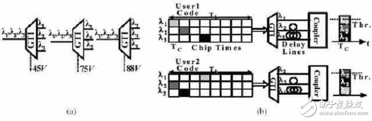
Figure 1(a) By changing the MEMS structure, the multiplexer obtains a periodic output wavelength with a slew rate of 10μs and a multiplexer with a bandwidth of 30nm. The FSR can also be adjusted from 0.6 nm to 1.2 nm. (b) The periodic shift of the GTI can also be used to perform hopping between orthogonal OCDMA codes.
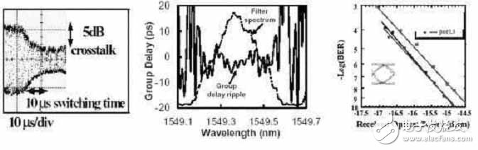
Figure 2b shows the group delay ripple GDR across the filter passband. The data shows that its peak-to-peak ripple is below 5 ps across the entire filter bandwidth and has a relatively uniform flat slope – this Explain that the filter effectively reduces chromatic dispersion. GDR is measured by the modulation phase method, fmod = 1 GHz, lstep = 0.01 nm.
Figure 2(a) shows a transition of 12 between ports 2 and 3 with a conversion time of 10 μs. (b) The group delay ripple GDR pattern across the GTI filter passband, whose peak-to-peak ripple is less than 5 ps across the entire filter bandwidth, GDR is measured using the modulation phase method, fmod = 1 GHz, lstep = 0.01 nm. (c) BER measurement of 10G modulated 1548 nm signal through each port. There is no distortion in the bit during the traversal of the CTI.
Figure 2c shows the BER measurement of a 10G modulated 1548 nm signal through each port. The results show that the power loss is less than 0.5 dB.
Fast code hopping test in a time-wavelength two-dimensional OCDMA system
Optical code division multiple access (OCDMA) technology has attracted more and more attention because of its ability to realize secure and asynchronous digital communication between multiple users [5]. One way to help traditional OCDMA systems eliminate the need for small chip time is to use a two-dimensional OCDMA architecture in which each bit is separated into chip times and a set of discrete wavelengths. Collection [6]. Figure 1b shows how an OCDMA bit is encoded in time domain and wavelength. Since the periodic period shift of the asynchronous orthogonal code is usually the orthogonal code itself, the periodic wavelength tuning characteristics of the GTI combined with the fast modulation speed of the MEMS driver will make these MEMS-based adjustable GTIs a good choice for the code hopping OCDMA system.
Test equipment
Figure 3 shows the test configuration diagram in the code hopping demo. Each data bit is programmed into a combination of three wavelengths (1543.2 nm, 1548 nm, 1552.8 nm) and 8 chips (100 ps per chip interval). If the data is "1", the 10Gb/s pattern generator produces a 100ps pulse in one bit period (800 ps), and no pulse if the data is "0". A fiber Bragg grating array (FBGA) acts as a fixed encoder to delay the wavelength of the associated codeword. The encoded data is then distributed to individual users through different lengths of fiber (~20 m).
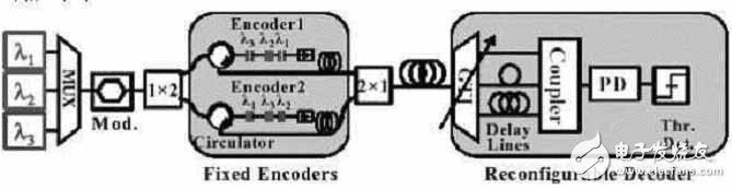
Figure 3: Experimental configuration diagram using GTI as a tunable decoder in a time-wavelength OCDMA system. The transmission rate is 1.25 Gb/s and each chip is 10 Gb/s.
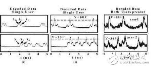
Figure 4: User 1 can be decoded by adjusting the voltage of the GTI to 30V. The voltage is adjusted to 80V and the second user will be decoded. Figures a and B show the encoding/decoding situation when only one user is present. Figure c shows the code hopping situation when there are two users.
The encoded data from the two users are grouped together and passed through an adjustable GTI decoder. The length of the fiber connected to the GTI output port is different, rearranging the user wavelength and producing a three-level peak pulse. The output of the receiver is a threshold detector that recovers 1.25 Gb/s of data. Figures 4a and b show that User 1 and User 2 data can be decoded by simply adjusting the voltage of the GTI without changing the delay line length. Figure 4c shows the situation where two users are present at the same time. When one user is decoded, the remaining users will generate noise for the previous user. Crosstalk from GTI is also similar to MAI.
When you think of the screen protectors of old, you're probably thinking of TPU. It's a flexible plastic that's a huge hassle to install . it's flexible, so it can go edge-to-edge on any phone, it has better impact protection than PET, and it has limited "self-healing" powers for small scratches. Brands like TUOLI offer TPU at very affordable prices,
On the other hand, TUOLI's comes in a few different styles depending on the look, feel, and features you want.
Tpu Screen Protector,Hydrogel Protective Film,Mobile Phone Screen Protector,Tpu Hydrogel Film,hydrogel protector, hydrogel sheet
Shenzhen TUOLI Electronic Technology Co., Ltd. , https://www.hydrogelprotectors.com