1 Introduction
With the widespread application of automotive electronic products in vehicles, the reliability of automotive electronic products has also received much attention. Vibration is an important factor that affects the reliability of automotive electronic products. If the vibration characteristics of automotive electronic products can be accurately predicted in the R & D design stage, it is of great significance to the reliability design of automotive electronic products. Finite element technology can be used to predict the vibration characteristics of automotive electronic products in the R & D and design stage, but for electronic products with complex structures, due to the complexity of the model, the uncertainty of material parameters, the nonlinearity of boundary settings, The influence of factors such as configuration requirements makes the simulation results less reliable. Therefore, improving the credibility of simulation analysis is the primary task of simulation workers today. In this paper, a modal simulation analysis and modal test are carried out on an automotive electronic controller with a complex structure, and the methods of geometric model modification, element type selection, and boundary condition setting in the simulation analysis are studied.
2 Introduction to the structure of automotive electronic controllers
The automobile electronic controller is composed of PCBA (integrated circuit board) and upper and lower shells, as shown in Figure 1 (to show the internal structure of the controller, part of the shell is cut away). When assembling the controller, first insert the PCBA into the lower housing along the slot on the housing, and then buckle the upper housing to the lower housing to complete the assembly. The controller is installed on the vehicle by bolting through the mounting ears on the housing and then fixed to the bracket.
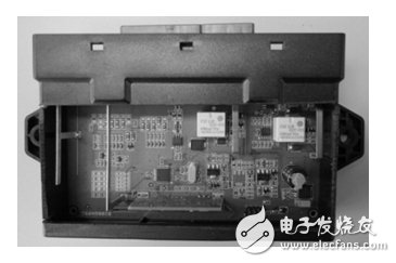
Figure 1: The physical picture of the controller
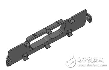
Figure 2: Modified model of the upper shell
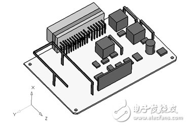
Figure 3: The revised model of PCBA
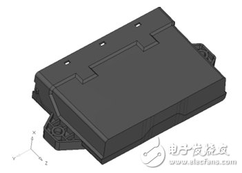
Figure 4: Modified model of the lower shell
3 Finite element modeling and simulation calculation
3.1 Geometric model correction
In actual work, it is found that the quality of the geometric model is determined by the modification of the geometric model. For a complex model, if the geometric model is not modified, the number of singular elements and the total number of elements will increase, resulting in a longer simulation analysis period, greater analysis cost, and even simulation analysis. There are hundreds of thousands of tiny holes and devices on the PCBA of the controller, and there are overly dense hard points and lines and tiny rounded corners on the case. Unable to complete analysis. Therefore, before meshing, first modify the geometric model of the controller. Geometric model correction work includes: removing smaller rounds and round holes; hiding overly dense curves and hard points; cutting irregular geometry; ignoring tiny electrical devices, etc. The modified geometric model of the controller is shown in Figure 2, Figure 3 and Figure 4.
Forehead Thermometer,Forehead Infrared Thermometer,Medical Forehead Thermometer,Noncontact Infrared Forehead Thermometer
Ningbo Anbo United Electric Appliance Co.,ltd , https://www.airfryerfactory.com