The emergence of the emerging field of semiconductor lighting has made engineers who specialize in the three fields of power electronics, optics and thermal management (mechanical engineering) become sought-after talents. At present, there are not many engineers with experience in the three fields, and this usually means that the background of the system engineer or the overall product engineer must be related to these three fields, and they also need to collaborate with engineers in other fields as much as possible. System engineers often bring their own habits or accumulated experience in the original field into the design work. This is similar to the situation encountered by an electronic engineer who mainly studies digital systems to solve power management problems: they may rely on Simple simulation, without directly testing the power supply on the test bench, wiring directly on the circuit board, because they did not realize that the switching regulator needs to carefully check the circuit board layout; in addition, if it has not been tested by the test bench, the actual working situation It is difficult to be consistent with the simulation.
In the process of designing LED lamps, when the system architecture engineer is an electronic power expert, or the power supply design is contracted to an engineering company, some common habits in standard power supply design will appear in the LED driver design. Some habits are useful because LED drivers are very similar to traditional constant voltage sources in many ways. These two types of circuits work under a wide input voltage range and a large output power. In addition, these two types of circuits are faced with different connection methods such as connecting to an AC power supply, a DC regulated power rail or a battery. Challenge.
Power electronics engineers are used to always want to ensure high accuracy of output voltage or current, but this is not a good habit for LED driver design. Digital loads such as FPGAs and DSPs require a lower core voltage, which in turn requires stricter control to prevent higher bit error rates. Therefore, the tolerance of digital power rails is usually controlled within ± 1% or less than their nominal value, and can also be expressed in absolute values, such as 0.99V to 1.01V. When introducing the design habit of traditional power supply into the field of LED driver design, the usual problem is: in order to achieve strict control of the output current tolerance, more power will be wasted and more expensive devices will be used, or both Of it.
Cost pressure
The ideal power supply is not high cost, the efficiency can reach 100%, and does not occupy space. Power electronics engineers are accustomed to listening to opinions from customers, and they will do their best to meet those requirements, trying to design the system within the smallest space and budget. LED driver design is no exception. In fact, it faces greater budget pressure because traditional lighting technology has been fully commercialized and its price is already very low. Therefore, it is very important to spend every penny under the budget. This is also where some power electronics designer engineers are "misleading" by old habits.
To control the accuracy of the LED current to be the same as the accuracy of the power supply voltage of the digital load, it will waste both electricity and cost. 100mA to 1A is the current range of most products, especially the current 350mA (or more precisely, the current density of the optoelectronic semiconductor junction is 350mA / mm2) is a trade-off between thermal management and lighting efficiency. The integrated circuit that controls the LED driver is silicon-based, so there is a typical band gap in the 1.25 V range. To reach a tolerance of 1% at 1.25V, a voltage range of ± 12.5mV is required. This is not difficult to achieve. There are many types of low-cost voltage reference circuits or power supply control ICs that can achieve this tolerance or better tolerance range, and the price is low. When controlling the output voltage, high-precision resistors can be used to feedback the output voltage at very low power (as shown in Figure 1a). To control the output current, you need to make some adjustments to the feedback method, as shown in Figure 1b. This is currently the only and simplest way to control the output current.
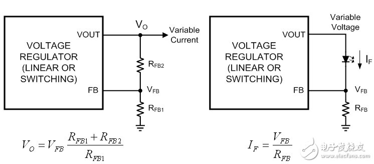
Figure 1a: Voltage feedback; Figure 1b: Current feedback
After in-depth research, you will find that one of the main disadvantages of this approach is that both the load and the feedback circuit are identical. The reference voltage is added to a resistor in series with the LED, which means that the higher the reference voltage or LED current, the more power the resistor consumes. Therefore, the reference voltage of the first-generation dedicated LED driver integrated circuit is much lower than the current product, which is similar to the battery charger. Lower voltage means lower power consumption, but also means smaller, cheaper, lower loss current sense resistors. In the simple low-end feedback environment shown in Figure 1b, 200mV is the conventional voltage selection. However, to achieve a tolerance of ± 1% at a reference voltage of 200mV, a very expensive integrated circuit is required, and the tolerance relative to the nominal reference voltage is ± 2mV. Although this is not impossible, higher accuracy requires higher costs. The tolerance of ± 2mV requires the production, testing, and binning technology required for high-precision voltage reference, and in this case, the additional cost should be spent on smarter LED drivers. The value of the new cost is the addition of a feedback loop, with which the light output (rather than the current output) can be used to control how the LEDs are driven.
Measuring light output
Just like digital product designers will adopt simulation to solve problems when they encounter uncertain problems in power supply design, system architects from power electronics engineers will think of high-precision output when designing LED lamps. LED manufacturers have made it clear that the luminous flux is proportional to the forward current. Use the same current to drive all LEDs, then each LED will produce the same luminous flux. Therefore, power electronics engineers will conclude that high-precision current is necessary. In this way, they forget that the lumen and lux value of the light output (rather than the ampere value) are the main points. Measuring current is easy, but relatively, measuring light requires large and expensive equipment, such as the integrating sphere shown in Figure 2, and most electronic engineers do not know much about the integrating sphere.
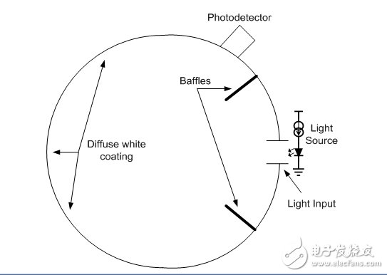
Figure 2: Cross section of optical integrating sphere
In addition, even if a current source with a tolerance of ± 0.1% (its price will be quite high) has a huge market value, it has no effect on producing a strict tolerance value in the actual light output. This can be determined by observing the bins of LED luminous flux. Table 1 shows the 350mA and 25 high-end cold white LEDs of the world's top three power photoelectric semiconductor manufacturers? The results of luminous flux binning under C conditions. Note that the last column is the average tolerance of each bin, not the tolerance of all luminous flux bins.
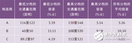
Table 1 High-end cool white LEDs of the world's top three power photoelectric semiconductor manufacturers at 350 mA and 25? The luminous flux binning result under C.
Calculate light output accuracy
Knowing that the LED light output from a single flux bin has a tolerance of ± 3% to ± 10%, the system engineer may therefore conclude that the drive current tolerance value must be as strict as possible. However, from a statistical point of view, this view is not correct. A common but incorrect assumption is that the overall tolerance of any value is equal to the simple accumulation of the values ​​under worst-case conditions. The tolerance of the current source supplying the LED and the tolerance of the LED luminous flux are independent of each other-they are independent of each other at the initial stage. For two uncorrelated factors X and Y, the overall tolerance Z is not the sum of the tolerances of X and Y, but should be calculated using the following expression:
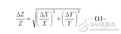
Table 2 and Figure 3 show the comparison between the overall tolerance and the assumed current source tolerance. At this time, it is assumed that the LED light output changes linearly with the forward current in the 350mA region.
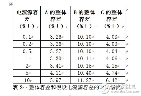
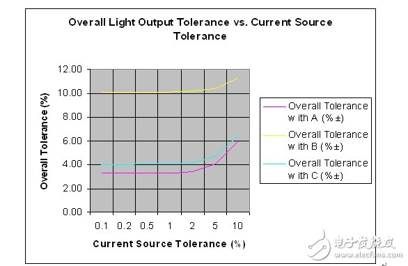
Figure 3: Comparison of overall tolerance and assumed current source tolerance.
According to equation (1), it can be found that the function of the lowest tolerance factor is greater than the others, and the actual overall tolerance value is much better than the tolerance of the various factors in the worst case, especially when one of the factors is far better than the other Factor time. It can be seen from Figure 3 that the most reasonable goal of the current source tolerance is to control it within the tolerance range of the LED light output. Remember: For cost reasons, many lamps use LEDs from different bins. Table 3 lists the maximum two, three, and four luminous flux tolerances of the same LED.
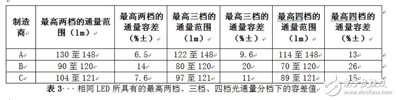
Table 3 Tolerance values ​​of the same two-level, three-level and four-level luminous flux of the same LED
The Samsung Note 8 Battery has a capacity of 3300mAh,battery type is lithium polymer,it comes with a special chip to protect your smart phone from over heating,short-circuit,over charging and over discharging.This replacement Phone Battery will 100% compatible with your Samsung Note 8.We also have other Samsung series batteries,such as Samung A8 battery,Samsung A9 Battery,Samsung S8 Battery,Samsung S8 Plus Battery, Samsung S9 Battery etc.Welcome your trial orders to test our quality and service.

Samsung Note 8 Battery
Samsung Note 8 Battery,Battery For Samsung Note 8,Galaxy Note 8 Battery,Samsung Galaxy Note 8 Battery
Shenzhen Hequanqingnuo Electronic Technology Co., Ltd. , https://www.hqqnbattery.com