Routing and switching are two important concepts in the network world. Traditional switching occurs at the second layer of the network, the data link layer, while routing occurs at the third layer, the network layer. In the new network, the intelligence of routing and the performance of switching are organically combined, and three-layer switches and multi-layer switches are widely used in the campus network. This article will introduce some basic concepts of routing and switching, which are divided into four parts: network hierarchy, switching, routing, and fully-switched campus network.
Network hierarchy
The definition of the network reference model gives a clear division of functional levels. The most commonly mentioned are the ISO OSI reference model and the TCP / IP protocol suite.
The OSI reference model defined by the International Organization for Standardization divides the computer network into seven levels according to functions. This is what we often refer to as a seven-level model or a seven-level structure. The direct benefit of network function layering is that these layers can do their job, and different layers of software and hardware devices developed by different manufacturers can be used together. One level of device updates or software rewrites will not affect other levels. Each level in the TCP / IP protocol system corresponds roughly to the ISO reference model. As shown below:
The middle layer of OSI, the fourth layer, performs the transmission function and is responsible for providing reliable data transmission from one computer to another. The Transport Layer (Transport Layer) is a layer of succession and succession. There are three layers below it, all of which are related to data transmission; there are also three layers above to provide functions related to network applications.
In the three layers under OSI. The physical layer is responsible for the actual transmission of data signals, the data link layer is responsible for frame transmission within the network, and the network layer is responsible for computer addressing and data transmission between networks.
In the three layers of OSI. The Application Layer (ApplicaTIon Layer) is the highest level, it is responsible for providing user operation interface, commonly used e-mail services in the Internet, file transfer services, etc. are provided by this layer. Presentation layer (PresentaTIon Layer) is responsible for data representation, such as encryption before sending data, decryption when receiving data, translation of Chinese and English, etc. are the functions provided by this layer. The Session Layer is responsible for establishing and terminating the data transmission of the network, and the conversion of computer names into addresses is also completed at this layer.
Traditional exchange is the concept of the second layer. The function of the data link layer is to transmit frames within the network. The so-called "intra-network" refers to the transmission of this layer does not involve inter-network equipment and inter-network addressing. The common understanding is that the transmission within an Ethernet and the transmission on a WAN dedicated line are all responsible for the data link layer. The so-called "frame" refers to the structure of the transmitted data. Generally, the frame has a frame header and a frame tail. The header has an active layer 2 address, and the frame tail usually contains check information. The content between the head and tail is the user. The data.
The data link layer covers many functions, so it is divided into two sub-layers, MAC (Media Access Control, media access control) layer and LLC (Logical Link Control) layer. The common two-layer standard of local area network and metropolitan area network is IEEE's 802 protocol. In wide area networks, protocols such as HDLC (High-level Data Link Control), PPP (Point-to-Point Protocol) and Frame Relay (Frame Relay) are widely used.
Routing is the concept of the third layer. The network layer is the most important in the Internet. Its function is end-to-end transmission. The end-to-end meaning here is that no matter how far apart two computers are, and how many networks are in between, this layer ensures that they can communicate with each other. For example, the commonly used PING command is a network layer command. When PING is enabled, it means that the function of the network layer is normal. Normally, the network layer does not guarantee the reliability of communication, that is to say, although the data can reach the destination under normal circumstances, the network layer does not make any correction and recovery even if an abnormality occurs.
The commonly used protocols at the network layer are IP, IPX, APPLETALK, etc., among which the IP protocol is the cornerstone of the Internet. In the TCP / IP protocol system, other auxiliary protocols at the third layer include ARP (Address Resolution), RARP (Reverse Address Resolution), ICMP (Internet Message Control), IGMP (Group Management Protocol), and so on. Since network interconnection devices all have a path selection function, we often put routing protocols such as RIP and OSPF at this layer.
exchange
When it comes to exchange, broadly speaking, any data forwarding can be called exchange. Of course, now we are referring to the exchange in a narrow sense, including only the forwarding of the data link layer. People who do networks understand that switching mostly starts with switches. Circuit switches have been used in communication networks for decades. The equipment used for frame switching, especially the large-scale use of Ethernet switches, is a matter of recent years.
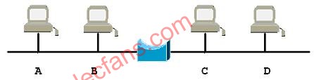
Understanding the role of Ethernet switches also starts with the principles of network bridges. Traditional Ethernet is shared. If there are four computers A, B, C, and D on the network segment, C and D can only listen passively while A and B are communicating. If the cable segments are separated (that is, miniaturized), A and B are on one segment, and C and D are on the other segment, then A and B can communicate while C and D can communicate, so the original 10M bandwidth is theoretically Talking becomes 20M. At the same time, in order to ensure that the two network segments can communicate with each other, you need to connect them with a bridge, which is a computer with two network cards, as shown in the following figure:
When the entire network is just started, the bridge to the network
The topology of the network is ignorant. At this time, suppose that A sends data to B. Because the network is broadcast, the bridge also receives it, but the bridge does not know whether B is on its left or right, and it performs the default forwarding, which is sent on another network card. This information. Although a useless forwarding was done, through this process, the bridge learns that the sender A of the data is on his left. After each computer on the network has sent data, the bridge is intelligent, and it knows which network segment each computer is on. When A sends data to B again, the bridge does not forward data, and at the same time, C can send data to D.
As can be seen from the above example, the bridge can reduce the chance of network conflicts. This is the main purpose of using the bridge, which is called reducing the collision domain. But the bridge can't stop the broadcast. The isolation of broadcast information depends on the three-layer connection equipment and router.
According to the idea of ​​miniaturization of cable segments, the more cable segments, the higher the available bandwidth. The extreme case is that each computer is on a separate cable segment. If there are ten computers on the network, a ten-port bridge is needed to connect them. However, the realization of such a bridge is not realistic, and the speed of software forwarding cannot keep up. So, with a switch, the switch is to hardware or firmware the above multi-port bridge to achieve lower cost and higher performance.
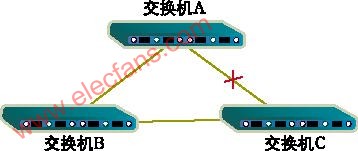
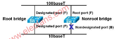
An important function of the switch is to avoid switching cycles, which involves STP (Spanning Tree Protocol, branch tree protocol). The function of the branch tree protocol is to avoid the cyclic transmission of data frames in the network formed by switches. As shown in the following figure, if there are redundant links in the network, the STP protocol now selects the root switch (Route Bridge), and then determines the path between each non-root switch to the root switch, and finally, the path All links are placed in the Forward state, and the connections between the remaining switches are redundant links, which are placed in the Block state.
Another important function of the switch is VLAN (Virtual LAN, Virtual Local Area Network). There are three main benefits of VLAN:
The separation of ports. Even on the same switch, ports in different VLANs cannot communicate. Such a physical switch can be used as multiple logical switches.
Network security. Different VLANs cannot communicate directly, eliminating the insecurity of broadcast information.
Flexible management. It is not necessary to change the port and connection line to change the network to which the user belongs, only the software configuration is enough.
VLANs can be divided by port or MAC address.
Sometimes, we need to maintain the consistency of VLAN configuration on the network formed by the switches. This requires the exchange of VLAN information between switches in accordance with VTP (VLAN Trunk Protocol, VLAN backbone protocol). The VTP protocol only runs on trunk ports, which are the ports between switches.
routing
A router is a connecting device between networks. One of its important tasks is path selection. This function is the core of router intelligence. It is implemented by the administrator's configuration and a series of routing algorithms.
There are dynamic and static routing algorithms. Static routing is a special kind of routing that is manually set by the administrator. Although manually configuring all the routes can make the network operate normally, it will also bring some limitations. After the network topology changes, the static route will not change automatically, and must be intervened by the network administrator. The default route is a kind of static route, which is also set by the administrator. When no routing table entry for the target network is found, the router sends the information to the default router (gateway of last resort). The dynamic algorithm, as the name implies, is a route calculated automatically by the router. RIP, OSPF, etc., which are often said to be typical representatives of dynamic algorithms.
In addition, routing algorithms can be divided into DV and LS. The DV (Distance, distance vector) algorithm transmits the routing information of the current router to the neighboring router, and the neighboring router adds this information to its own routing table. The LS (Link State) algorithm transmits link state information to all routers in the domain. The receiving router uses this information to construct a network topology map and uses the shortest path priority algorithm in graph theory to determine the route. In contrast, the distance vector algorithm is relatively simple, while the link state algorithm is more complex, and it takes up more CPU and memory. But because the link state algorithm uses its own calculation results, it is relatively difficult to generate routing loops. RIP is a typical representative of DV-type algorithms, and OSPF is a representative protocol of LS.
The four most common routing protocols are RIP, IGRP, OSPF, and EIGRP.
RIP (RouTIng InformaTIon Protocols) is the most widely used distance vector protocol. It was developed by Xerox in the 1970s. At the time, RIP was part of the XNS (Xerox Network Service, Xerox Network Service) protocol suite. The TCP / IP version of RIP is an improved version of the Xerox protocol. The biggest feature of RIP is that it is very simple regardless of the implementation principle or configuration method. RIP calculates routes based on the number of hops, and periodically sends update messages to neighbor routers.
IGRP is a CISCO proprietary protocol and is only implemented in CISCO routers. It also belongs to the distance vector protocol, so it has something in common with RIP in many places, such as broadcast updates and so on. The biggest difference between it and RIP is in measurement methods, load balancing and other aspects. IGRP supports weighted load balancing on multiple paths so that the network bandwidth can be used more reasonably. In addition, unlike RIP which only uses hops as the measurement basis, IGRP uses a variety of parameters to form a composite measurement value, which can include factors such as bandwidth, delay, load, reliability, and MTU (Maximum Transmission Unit) Wait.
The OSPF protocol was developed in the late 1980s and became an industry standard in the early 1990s. It is a typical link state protocol. The main features of OSPF include: support for VLSM (Variable Length Subnet Mask), fast convergence, low bandwidth occupancy rate, etc. The OSPF protocol exchanges link state information between neighbors so that the router can establish a link state database (LSD). After that, the router uses the SPF (Shortest Path First, shortest path first) algorithm to calculate the routing table based on the information in the database The main basis is bandwidth.
EIGRP is an enhanced version of IGRP, which is also CISCO's proprietary routing protocol. EIGRP uses the DUAL update algorithm. To a certain extent, it is similar to the distance vector algorithm, but has a shorter convergence time and better operability. As an extension to IGRP, EIGRP supports a variety of routable protocols, such as IP, IPX, AppleTalk, etc. When running in an IP environment, EIGRP can also make a smooth connection with IGRP because their measurement methods are consistent.
The above four routing protocols are all intra-domain routing protocols, and they are usually used inside autonomous systems. When connecting between autonomous systems, inter-domain routing protocols such as BGP (Border Gateway Protocols) and EGP (External Gateway Protocols) are often used. The inter-domain routing protocol currently used on the Internet is BGP version 4.
Convergence is an important issue encountered when selecting routing algorithms. Convergence time refers to the time from when the topology of the network changes to when all related routers on the network are aware of the change and make changes accordingly. The shorter this time, the less disturbance the network changes will have on the entire network. If the convergence time is too long, routing loops will occur.
In the above several intra-domain routing algorithms, the convergence time of RIP and IGRP is relatively long, on the order of minutes; OSPF is shorter and can converge within tens of seconds; EIGRP is the shortest, after the network topology changes, a few seconds Convergence can be achieved.
Full-exchange campus network
The traditional campus network is a router and switch structure. As shown in the following figure, the switch is responsible for the internal transmission of the network, dividing VLANs to ensure the security and flexibility of the second layer, and the router completes the addressing and data forwarding between the networks.

Generally, the performance of routers is worse than switches, because routers are based on software look-up table forwarding, and switches can implement hardware straight-through forwarding. But in the traditional campus network, the router will not become the bottleneck of the network. Because 80% of the data volume is communication within the network, only 20% of the data is for remote access, that is, most of the information passing through the switch does not pass through the router. This is the 80/20 traffic model of traditional networks.
In recent years, due to the rise of the Internet / Intranet computing model, applications have been centrally managed, rather than being scattered in the network of various departments as before, and the traffic model of the campus network has changed greatly. A lot of network access is remote, that is, it has to pass through the router. This is called the new 20/80 flow model. Therefore, the router has gradually become the bottleneck of the network.
In order to solve this problem technically, network manufacturers have developed three-layer switches, also called routing switches. It is a combination of the performance of traditional switches and the intelligence of routers. The routing is still done by the router, but the result of the routing is kept in the routing cache by the switch. In this way, the first data packet in a data flow passes through the router, and all subsequent data packets are directly forwarded by the switch table lookup. Thanks to hardware forwarding, Layer 3 switches can achieve wire-speed routing, as shown in the following figure.

The Layer 3 switches produced by many manufacturers are themselves a combination of switches and routers. For example, Cisco 5000, 5500, and 6500 series switches can be equipped with routing modules to achieve Layer 3 functions.
As a result, the inside of the campus network is dominated by switches and Layer 3 switches. The fully-switched campus network adapts to the new traffic model, completely overcomes the bottleneck of routers in traditional networks, and greatly improves the efficiency of the network. At the same time, the router is not unemployed and is still used in remote connection, dial-up access and other occasions.
In the first part of this article, we reviewed the hierarchical structure of the network. Next, we discussed the principles of traditional routing and switching. Finally, we introduced how to combine the advantages of routing and switching in the current campus network to best meet the user's traffic model. .
Routing, switching, and routing switching are the three main issues in this article.
Due to space limitations, I will not repeat the specific protocol. Sometimes, understanding the protocol workflow and specific equipment, such as Cisco routers and switches, is very helpful for understanding the principles of the network.
A motor with gearbox is a mechanical device utilized to increase the output torque or change the speed (RPM) of a motor. The motor's shaft is attached to one end of the gearbox and through the internal configuration of gears of a gearbox, provides a given output torque and speed determined by the gear ratio.
Motor with gearboxes are used in many applications including machine tools, industrial equipment, conveyors, and really any rotary motion power transmission application that requires changes to torque and speed requirements.
motor with gearbox,motor and gearbox,24v dc motor with gearbox,1hp motor with gearbox,12v electric motor with gearbox,small electric motors with gearbox
Shenzhen Maintex Intelligent Control Co., Ltd. , https://www.maintexmotor.com