The first part of this series introduced the line-commutated converter (LCC), and now we'll dive into the voltage source converter (VSC) and compare it with LCC. VSC has become the preferred choice in modern power systems due to several advantages. First, VSCs are more cost-effective because of their simpler design and easier implementation. They also support bidirectional current flow, which makes it easier to reverse the direction of power transmission. Additionally, VSCs can independently control both active and reactive power on the AC side, offering greater flexibility. Unlike LCCs, which depend on the AC grid for commutation, VSCs can operate without a strong AC system, allowing them to supply passive loads and even perform black-start operations. The use of insulated gate bipolar transistors (IGBTs) eliminates the need for complex commutation processes required by thyristors, enabling more efficient and flexible operation.
Table 1 provides a detailed comparison between LCC and VSC. While VSC typically operates at voltage levels ranging from 150kV to 320kV, some advanced systems can go as high as 500kV. There are various types of VSC, including two-level, three-level, and modular multilevel converters. Let's take a closer look at these different configurations.
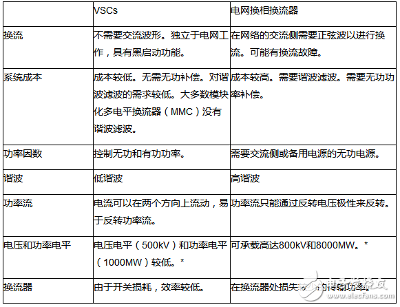
* Reference: "A review of LCC-HVDC and VSC-HVDC technologies and applications," presented at the 16th International Conference on Environmental and Electrical Engineering of the Institute of Electrical and Electronics Engineers (IEEE).
Table 1: Inverter Comparison
Two-Level Voltage Source Converter
As shown in Figure 1, the two-level VSC consists of IGBTs connected in parallel with reverse-biased diodes. Each valve is made up of multiple IGBT-diode assemblies in series. Pulse width modulation (PWM) is used to control the IGBTs, shaping the output waveform. However, since IGBTs switch multiple times during PWM, switching losses occur, and harmonic distortion becomes a concern.
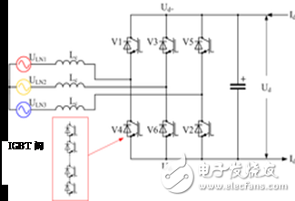
Figure 1: Two-Level VSC (HVDC Inverter Image courtesy of Wikipedia)
Three-Level Voltage Source Converter
As seen in Figure 2, the three-level VSC improves upon the two-level design by reducing harmonics. It uses four IGBT valves per phase, with two diodes used for voltage clamping. These diodes can be replaced with IGBTs for better controllability. By turning on the top two IGBTs, a higher voltage level is achieved. Activating the middle pair results in an intermediate or zero voltage level, while the bottom pair being open produces a lower voltage level.
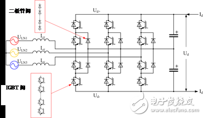
Figure 2: Three-Level VSC (HVDC Inverter Image courtesy of Wikipedia)
Modular Multilevel Converter
Unlike the two-level and three-level VSCs, the Modular Multilevel Converter (MMC) uses multiple inverter modules, each equipped with its own smoothing capacitor. Instead of using a single valve with multiple IGBTs, the MMC employs cascaded inverter modules, each representing a specific voltage level. These modules can be half-bridge or full-bridge type converters.
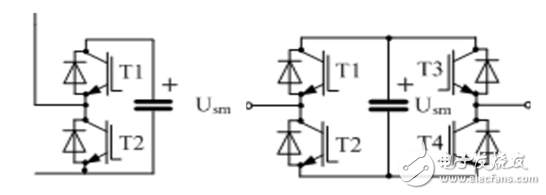
Figure 3: Modular Inverter Type (HVDC Inverter Image courtesy of Wikipedia)
The MMC significantly enhances harmonic performance, often eliminating the need for external filters. It is also more efficient than traditional VSCs because it reduces switching losses. This efficiency makes it ideal for high-voltage direct current (HVDC) applications.
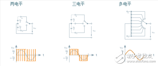
Figure 4: Waveform Output (Image courtesy of SVC PLUS VSC technology)
To monitor key parameters like power factor, voltage, and current, signals are measured on both the AC and DC sides of the station. Once collected, this data is sent to the inverter control device, which adjusts the system to maintain stable power levels and proper power factor. A protective relay system or intelligent electronic device (IED) helps gather and process these signals, as shown in Figure 5.
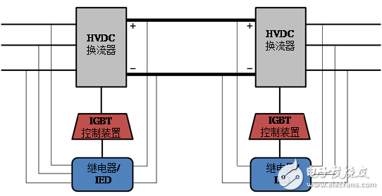
Figure 5: Signal Interpretation
Isolated current and voltage measurements using fully differential isolation amplifiers are a common reference design for measuring both AC and DC signals. This design guide explains how to use an isolated op-amp to adjust signal amplitude, reject common-mode voltage, and reduce noise. An MCU with built-in ADC then processes the signal. Based on the waveform, the inverter control system adjusts the phase and voltage levels to ensure stability and reliable performance.
The Mylar Speaker solutions come in a variety of shapes and sizes. We can provide various mounting configurations and performance alterations to fit any industrial application. Our Mylar speakers produce excellent sound output (dB) at specified frequency ranges. The unique characteristics of a Mylar cone allow us to keep tight tolerances during the manufacturing process. Additionally, Mylar is easily and consistently moldable, creating a cost-effective solution, time after time. It`s also beneficial in applications that are exposed to excessive moisture or humidity since Mylar has a high resistance to environmental factors.
Mylar Speaker,Mylar Tweeter,Mylar Cone Speaker,Cellphone Mylar Speaker
Jiangsu Huawha Electronices Co.,Ltd , https://www.hnbuzzer.com